| Author: |
Torsten Funk |
| Website: |
www.torsten-funk.de |
Goal of this tutorial:
Explaining all the basics of sculpties and creating a template which can be used to generate Sculpties quickly.
Hint:
At the end of this tutorial you can download a template as .blend file. If you want to create Sculpties you can use this file as template. Otherwise you can use the cylinder and the material in other .blend files. You only have to deform the object and bake a new sculpt map.
For this tutorial you need:
- Blender (> v2.5)
Hint:
Click the Screenshots to see them big!
Click the Screenshots to see them big!
Start Blender and in the top menu select
File > Load Factory Settings.
This gives you the default settings which are necessary for this tutorial.
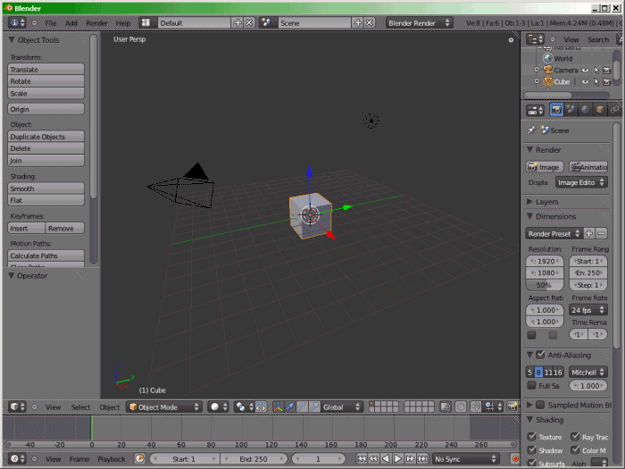

As we don't need this cube you can delete it by pressing the key DEL.

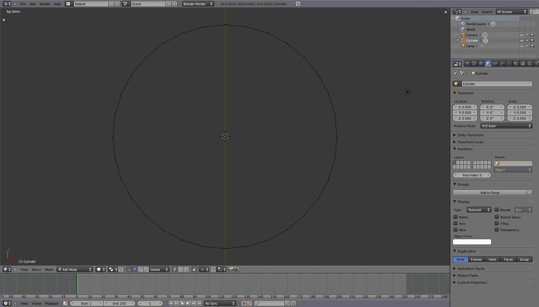
Now we wanna create a cylinder. It is important that the cylinder will be made of 33 rings vertically with 32 vertices on each ring - so 33*32=1056 Vertices.
To get exactly these values it is recommoned to extrude the cylinder out of a circle.
At first create a circle. Therefore go into the top menu and choose Add > Mesh > Circle.
Remark: You can find the technically details why these values are necessary on this website:
Sculpted Prims: Technical Explanation - Second Life Wiki

65*16=1040 Vertices
129*8=1032 Vertices
Sphere:
32*34
Cube Oblong:
Add Plane. Subdivide twice, remove vertices inside
LOD:
Set the radius of the circle to 5.

Vertices: 8
We don't need the right side bar any longer, so you can hide it by pressing T.

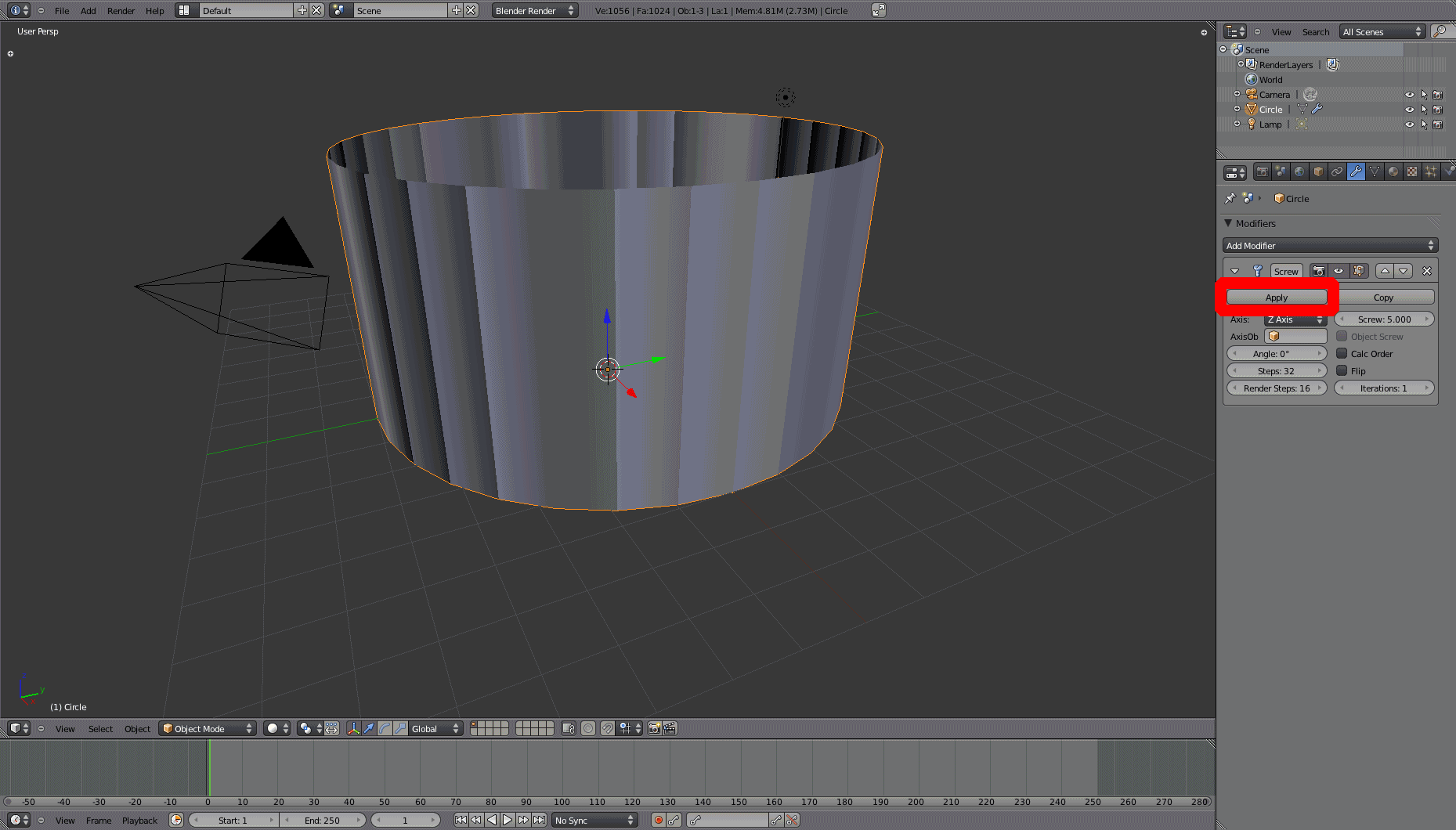
Next we need a Screw modifier which will extrude the circle 32 times. You can find this tool in the Modifiers section of the Properties.

Press the button Add Modifier > Screw to add a new Screw modifier.

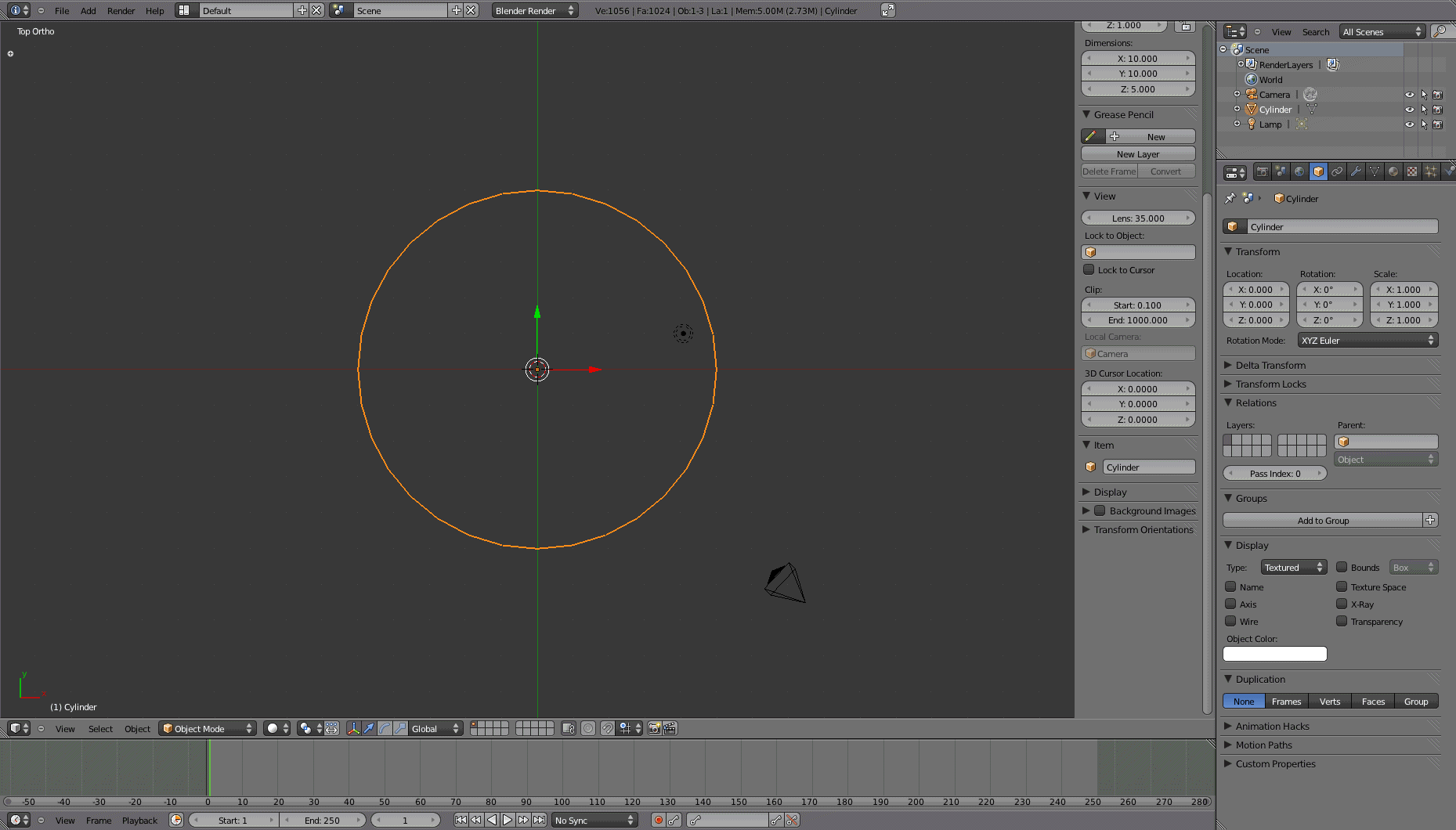
Set a Screw Offset of 5.00. That defines the height of the cylinder.
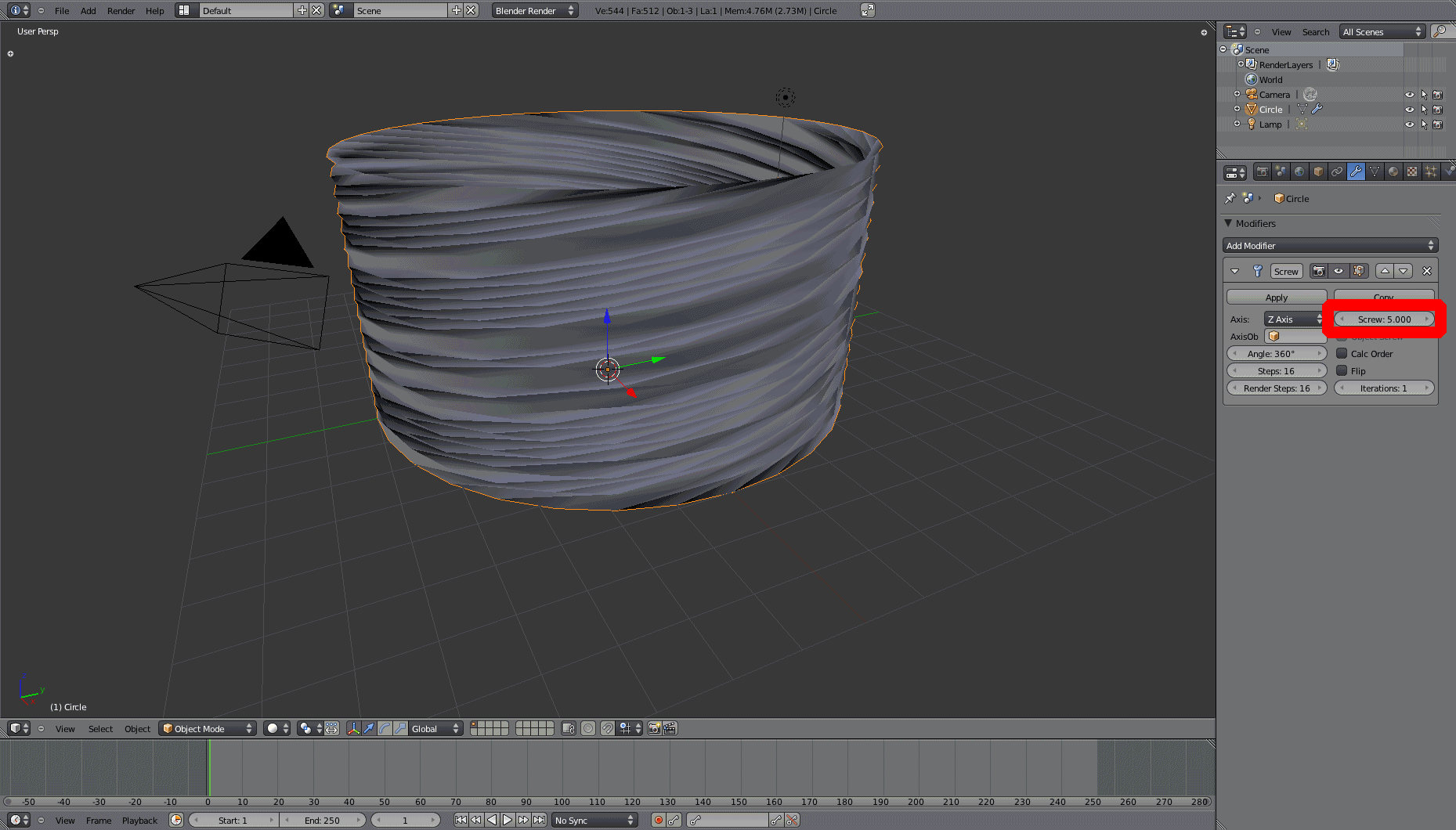
10
Set the screw Angle to 0°. This is the angle of climb of each revolution. Because we don't need a screw but a straight cylinder this has to be 0°.

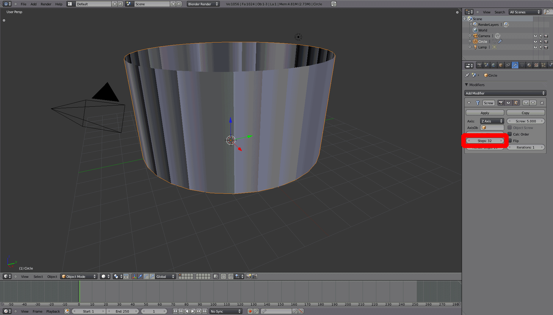
This is the number of steps in the revolution. Set it to 32. The circly will remain so we will get 33 rings.
64
LOD: 8
When you made all the settings correct press the button Apply.
LOD:
Leave Edit Mode
Multiresolution
2* Subdivide
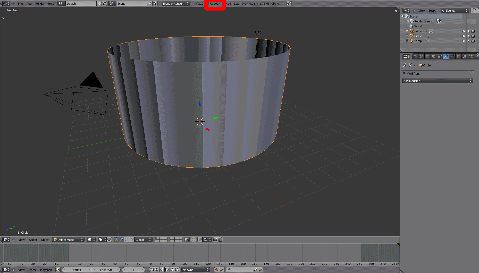
If you made everything correct Blender should show you that the cylinder is made of 1024 Faces. Whis is exactly what we need!
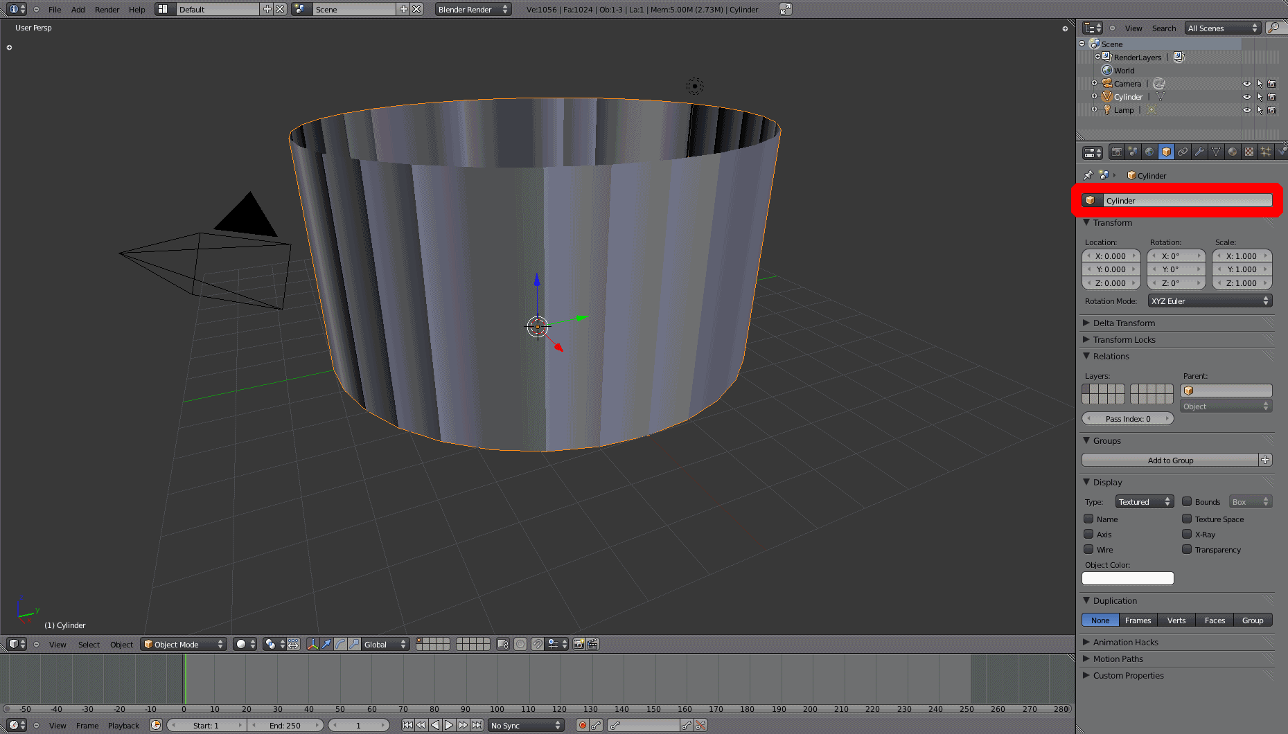
Now the object needs a name. Therefore go into the Object Buttons.

Type in a new name, e.g. Cylinder.
CubeOblong64
In the next steps you have to mark seams. They are necessary for the unwrapping process later. Blender gives better results on unwrapping when an object has defined seams.
At first switch to Top View by pressing the key Num7.
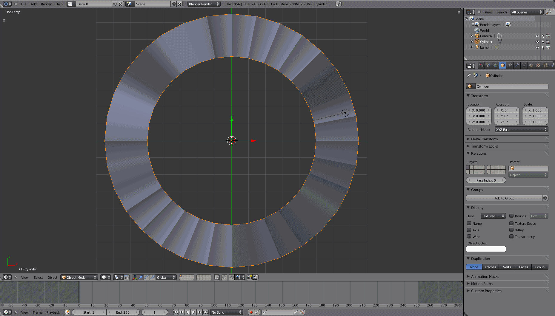
For selecting vertices exactly you better switch to the ortographic view by pressing the key Num5.
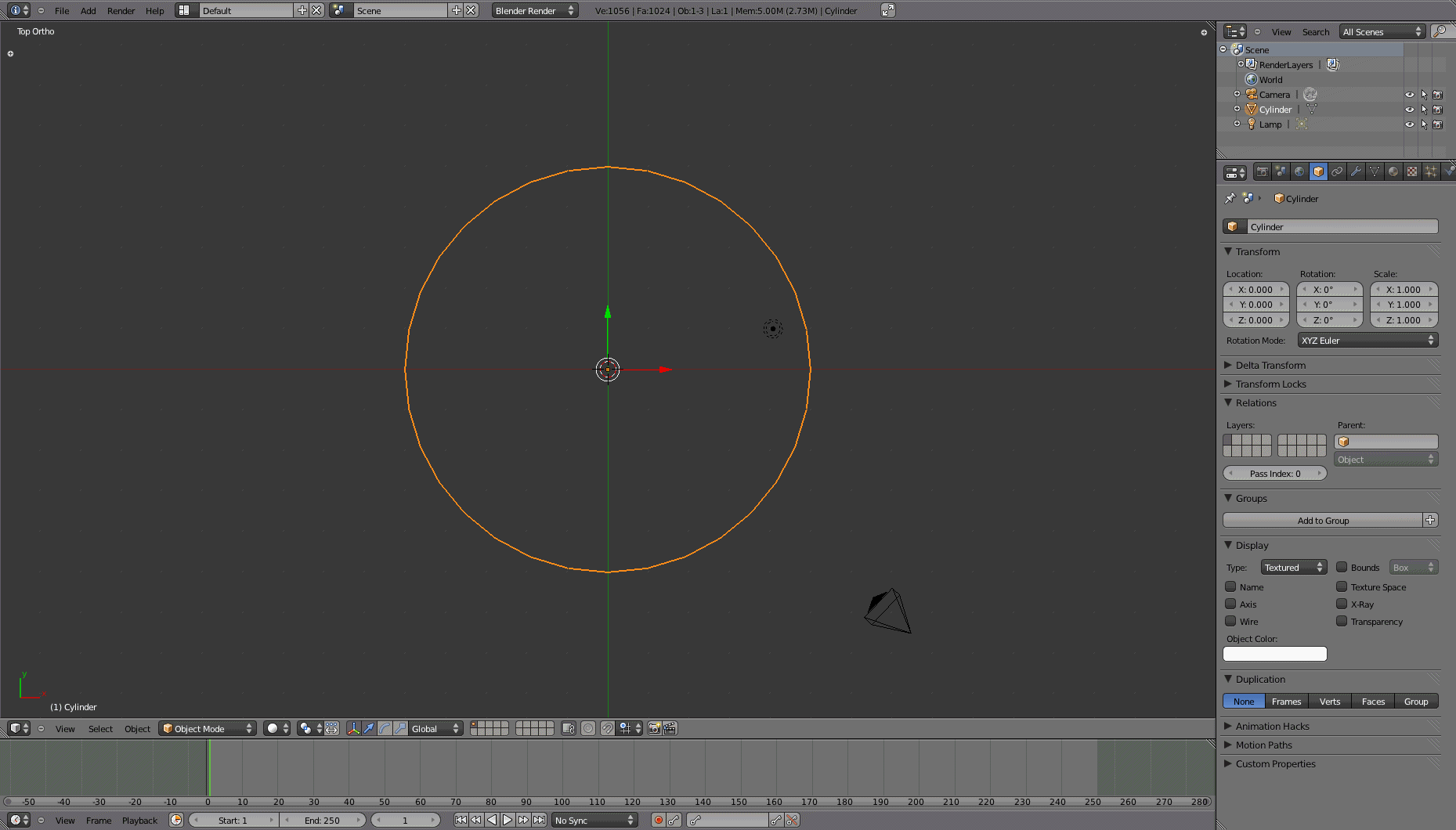
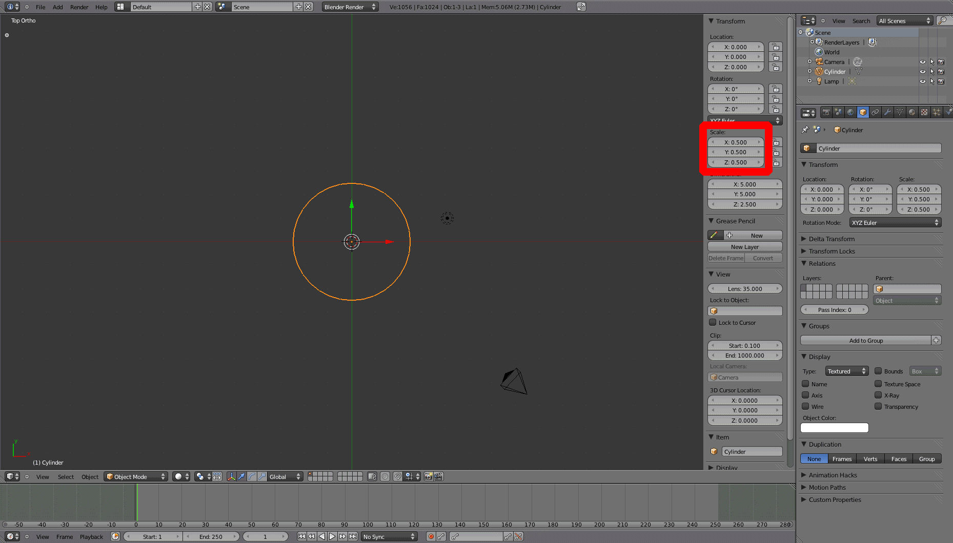
Lets display the Transform Properties by pressing the key N.
Change the scaling of your cylinder to
X = 0.500
Y = 0.500
Z = 0.500
This is necessary if you work on a set of several sculpties (e.g. a dragon). In your Second Life viewer you would have to set the size of each sculpt, and they all need to have the same size ratio. So you better start here with the same scaling as the Build window in Second Life.
vllt. besser: Dimensions to 0.5 und apply Scaling.
In the next steps you have to check and correct the face normals. Therefore switch to Edit Mode by pressing the key TAB.
Between four vertices there is a face (aka quads). Your cylinder has 1024 faces. Each face has an orientation. That is a vector which is perpendicular to the face. This orientation vector is called Face Normal.
Because a flat face has two sides a face normal of your cylinder can face inside or outside. A face normal indicates on which side of the face the texture will be mapped.
Blender usually sets the face normals wrong, or better not as we need it. Thats why you have to check and correct them now. In this case here they have to face outside.
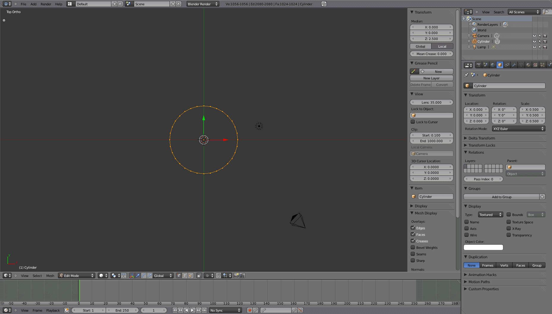
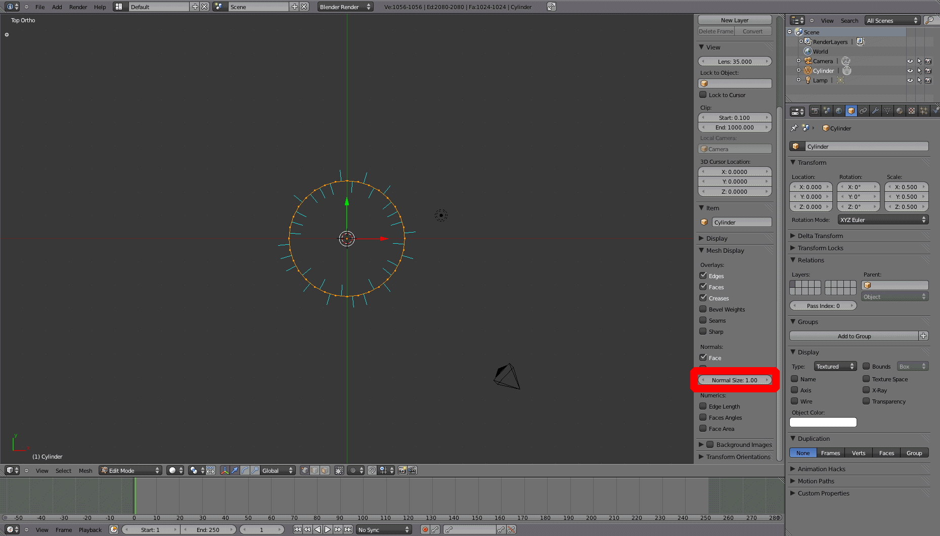
Now lets diplay the face normals - just activate Face in the Normals section. The top view is perfect to check them.

This is just to see them better if necessary. Just increase the Normal Size, e.g. to 1.00.
As you can see some normals face inside.
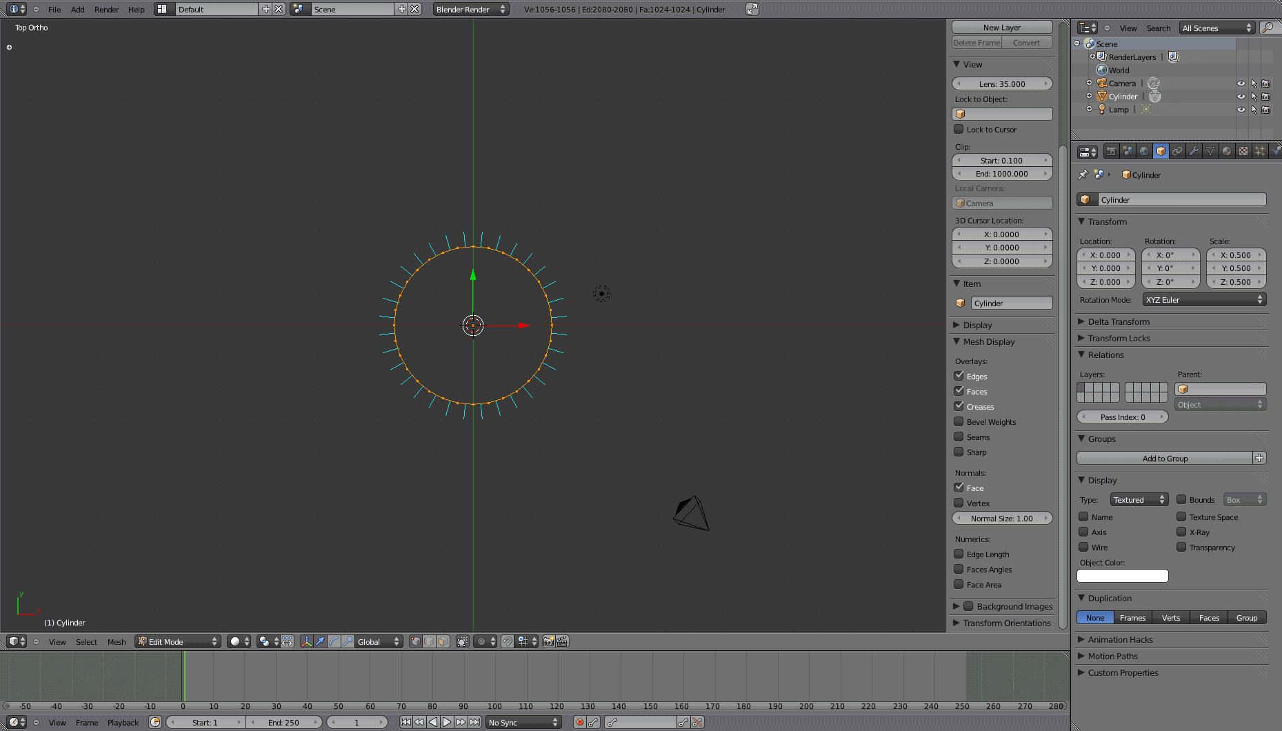
Blender has a feature to recalculate the normals either to outside or inside. If you press CTRL+N now the normals should be all calculated to outside.
Hint: If they were calculated to inside you can flip them with W-8. Both features can also be found in the Tools side bar which we hide in step 5.
All normals face outside now, so you can hide the normals again. Just deactivate Face in the Normals section.
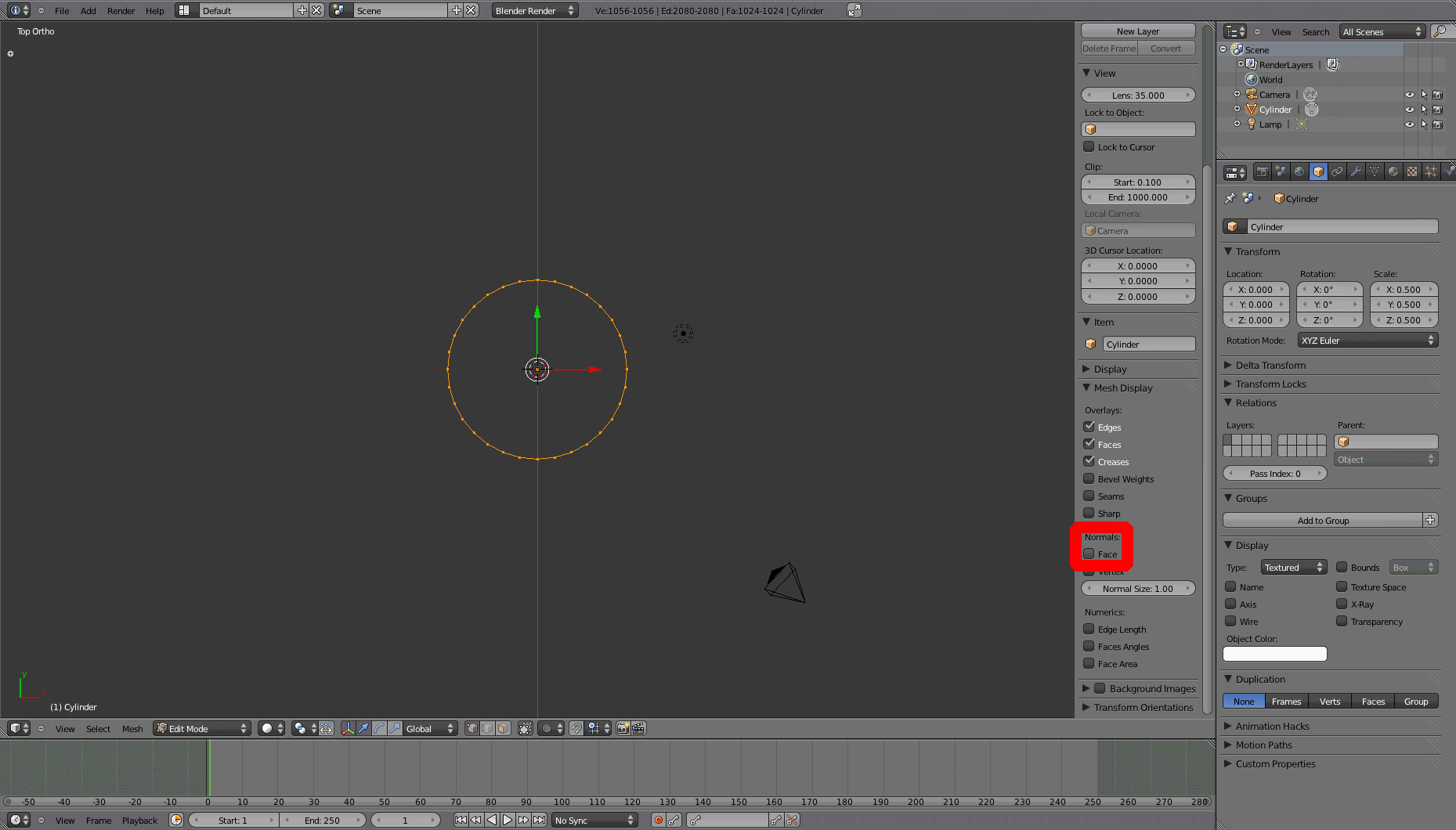
You don't need the Transform-Properties any longer, so hide them by pressing the key N.
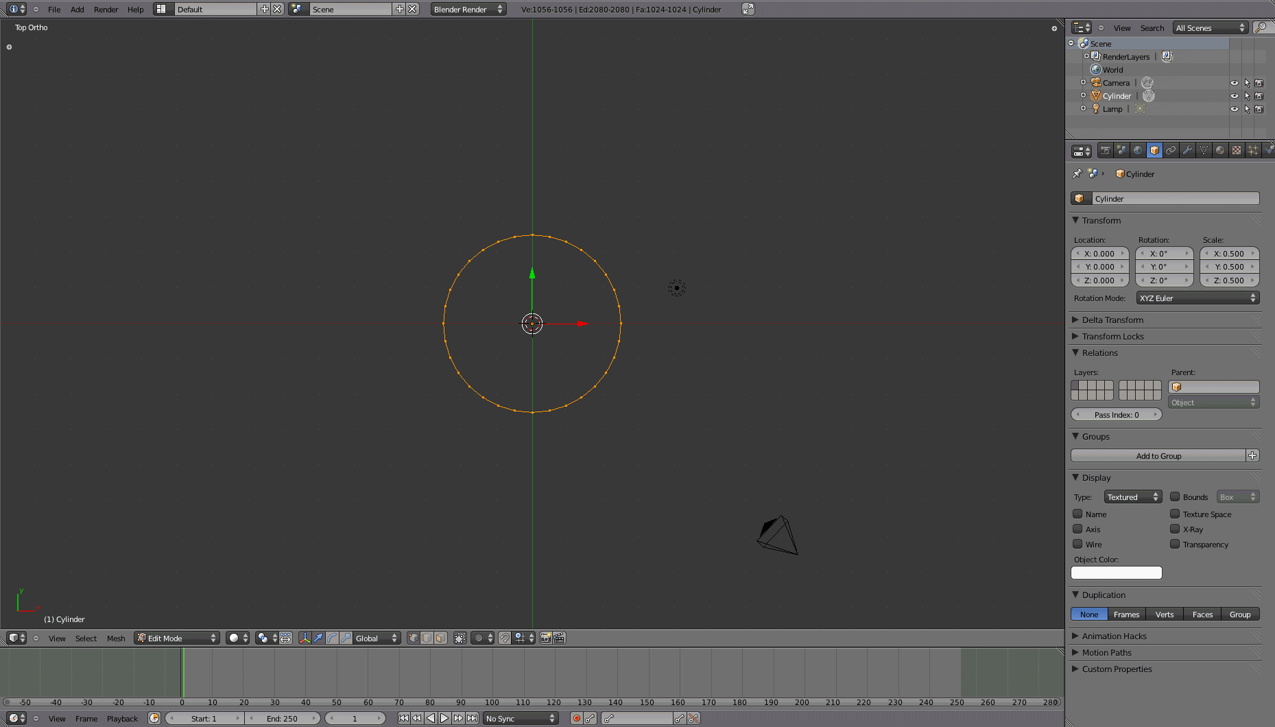
Just to see your object better zoom into it with your mouse wheel.

In the next steps you will mark the two seam which are necessary for the upcoming unwrapping. One seam for horizontal, one for vertical.
At first deselect all vertices by pressing A.
This feature is usually active and allows you to select only the vertices which you see - not those which are hidden on the back side of the object.
But you have to select hidden vertices now too, so deactivate this feature.

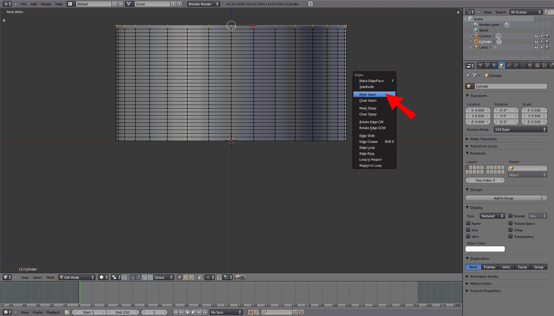
Press B and draw a border around the upper vertice. That will select all vertices behind it too.
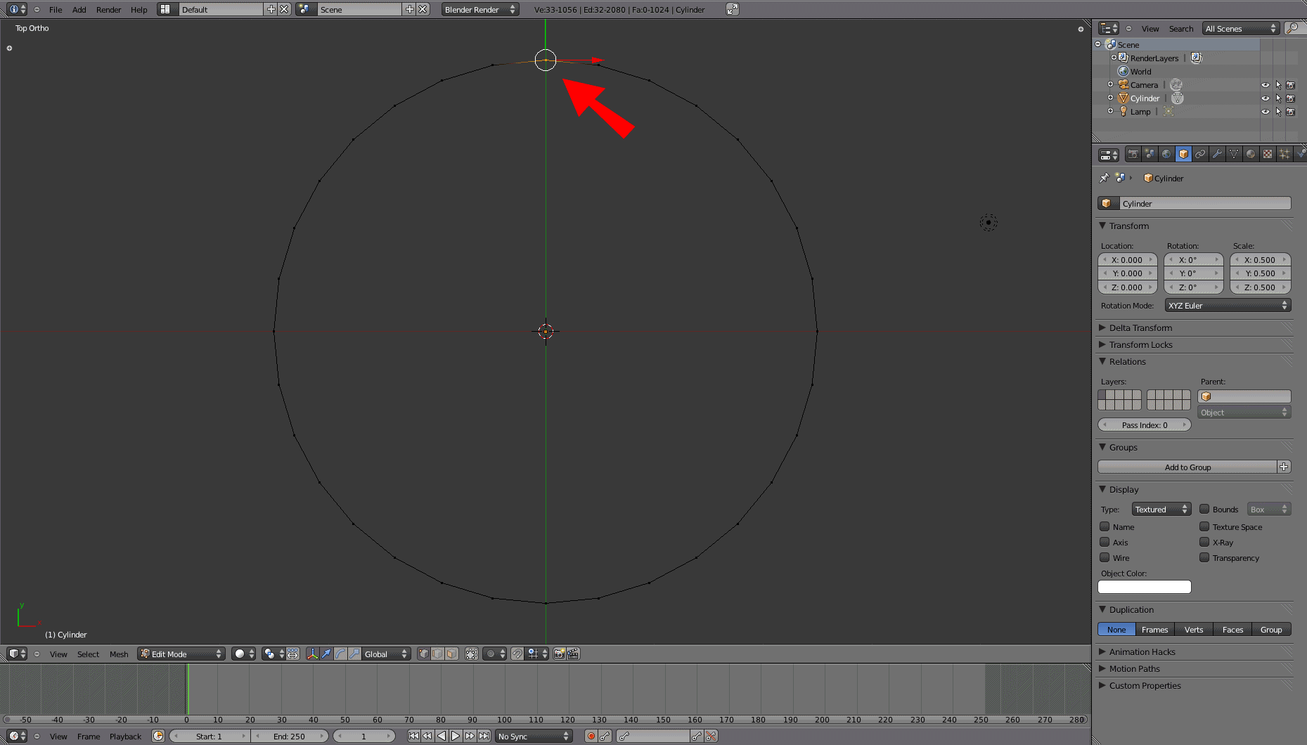
top right corner
Press CTRL+E > Mark Seam. Then all selected vertices (which are in a row) are defined as the vertical seam of your cylinder.
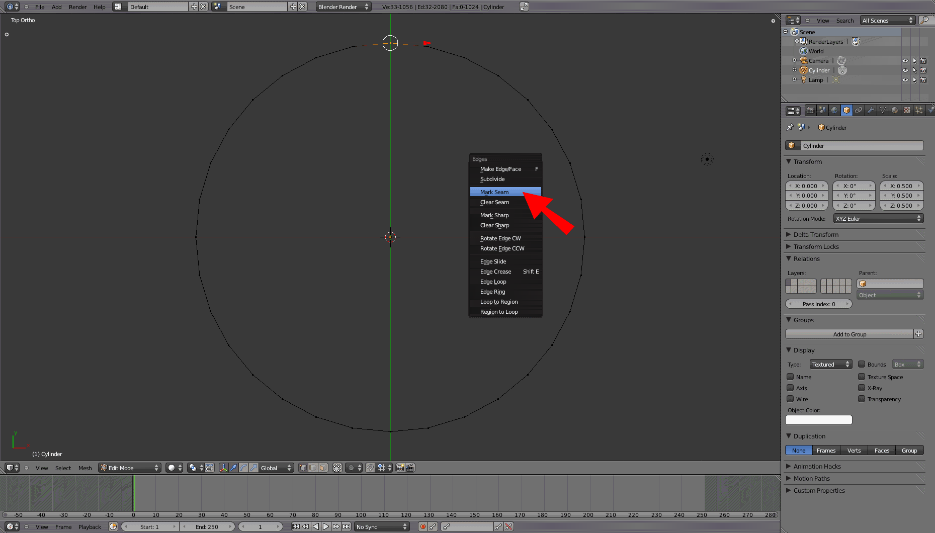
Deselekt all vertices now by pressing key A.

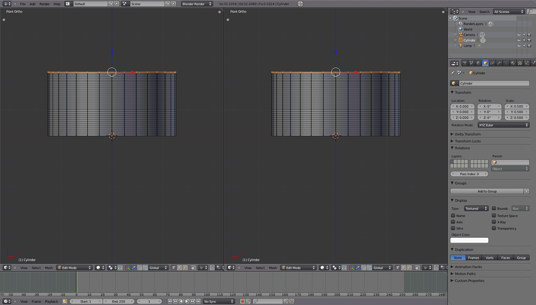
By pressing key Num1 you will switch to Front View, which is perfect to mark the horizontal seam.

Press B and draw a border around the upper ring of vertices. That will select all vertices behind it too.
Or try the ring selection with ALT+RMB on an upper edge.
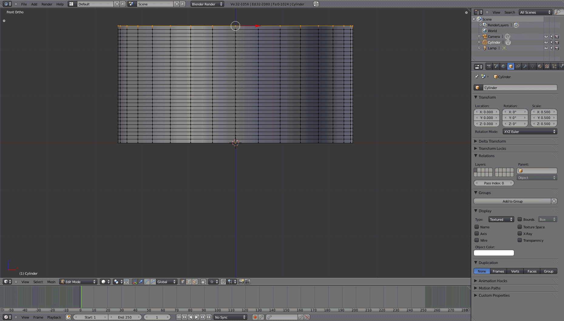
Press CTRL+E > Mark Seam. Then all selected vertices (which are in a ring) are defined as the horizontal seam of your cylinder.
CTRL+E-A
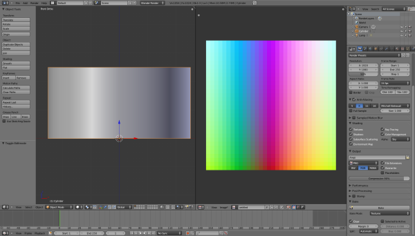
In the next steps you have to make an UV-Unwrapping to create a UV-Map.
Therefore split the 3D view.
Switch one half to the UV/Image Editor.
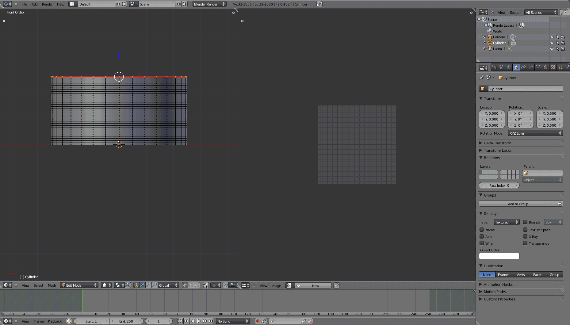
Press A twice.
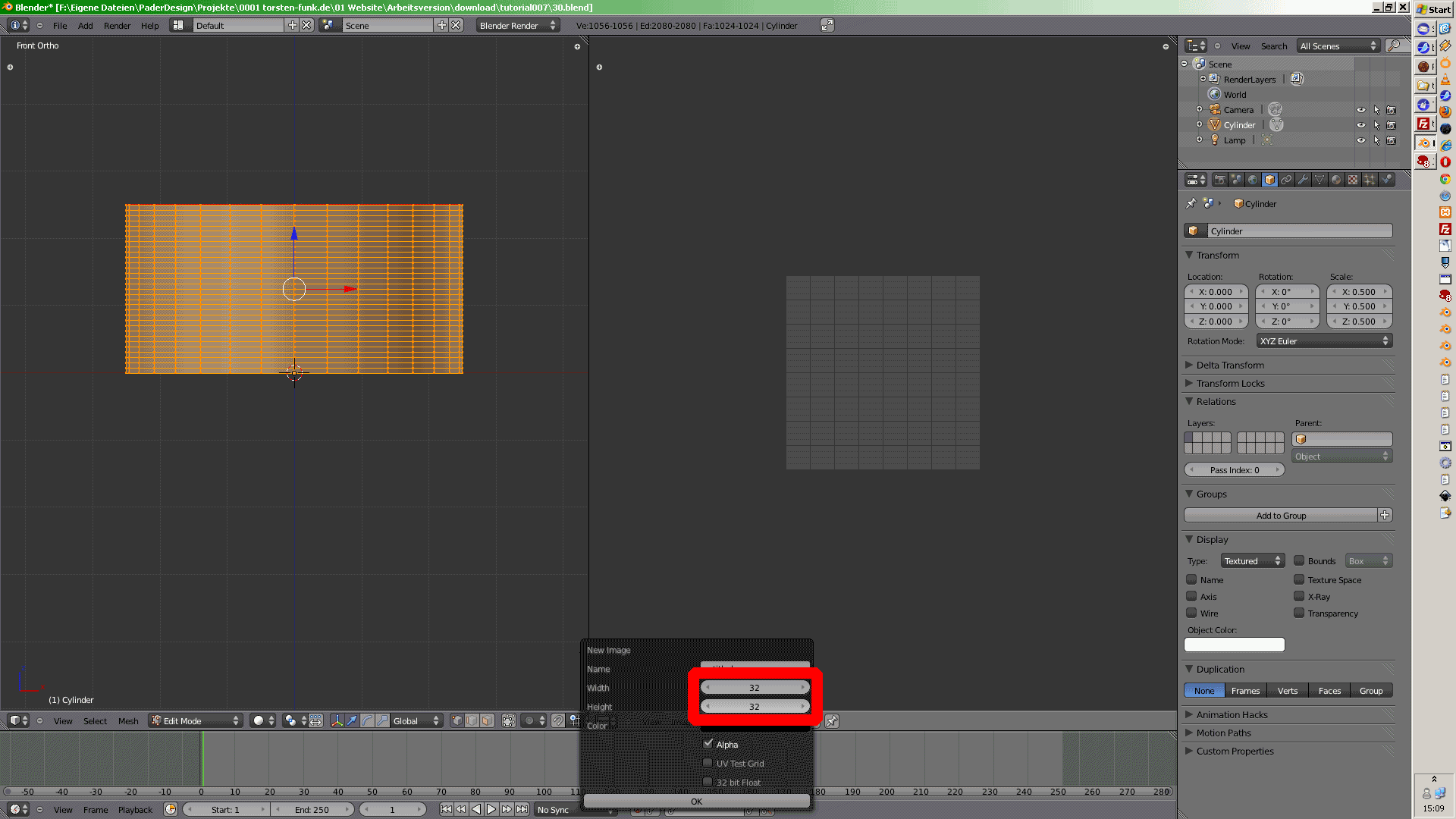
To adjust the faces of the UV Map exactly to the pixels of the image it is pretty helpful to have an image with 32*32 px and let each face snap to one pixel while scaling the UV Map.
So create a new image by
choosing Image > New,
pressing ALT+N or
clicking the button NEW.

Choose a size of
Width: 32
Height: 32
and apply with OK.
16*64
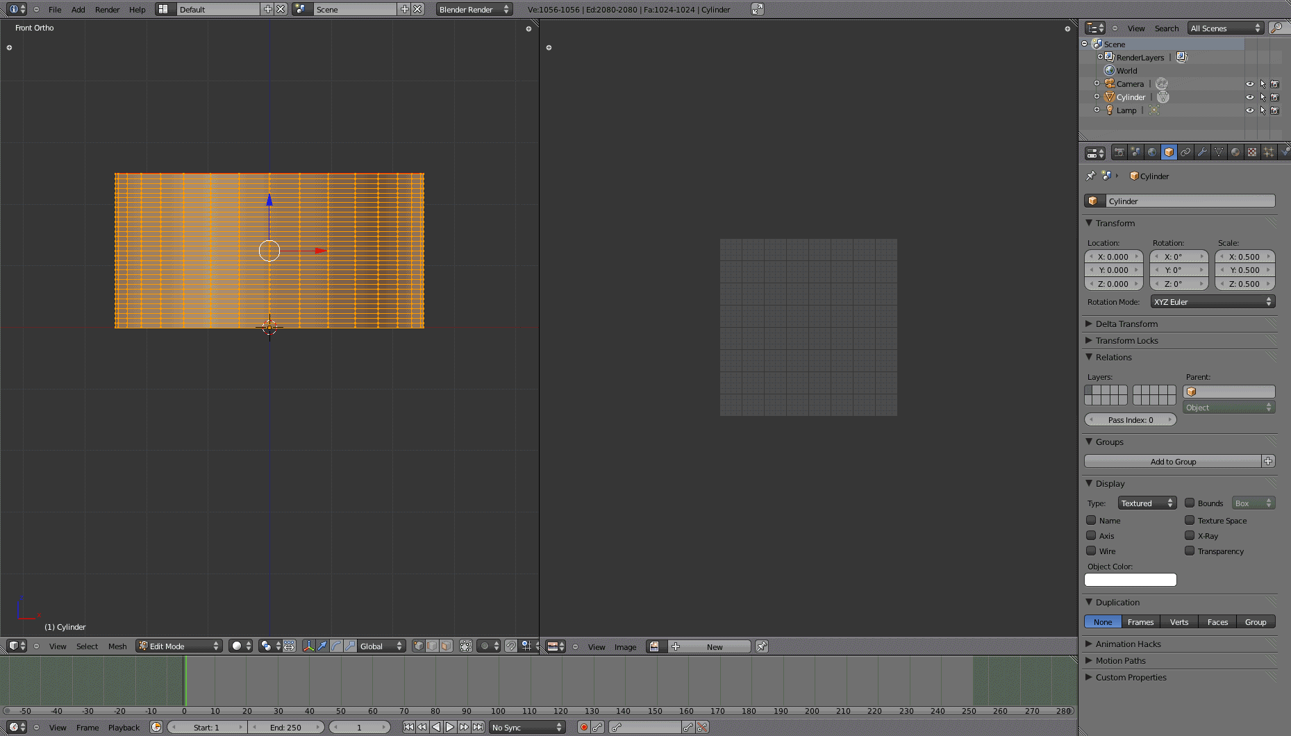
Now you have to unwrap the surface of your cylinder. Thats like unwrapping the globe to a world map.
Press U > Cylinder Projection.
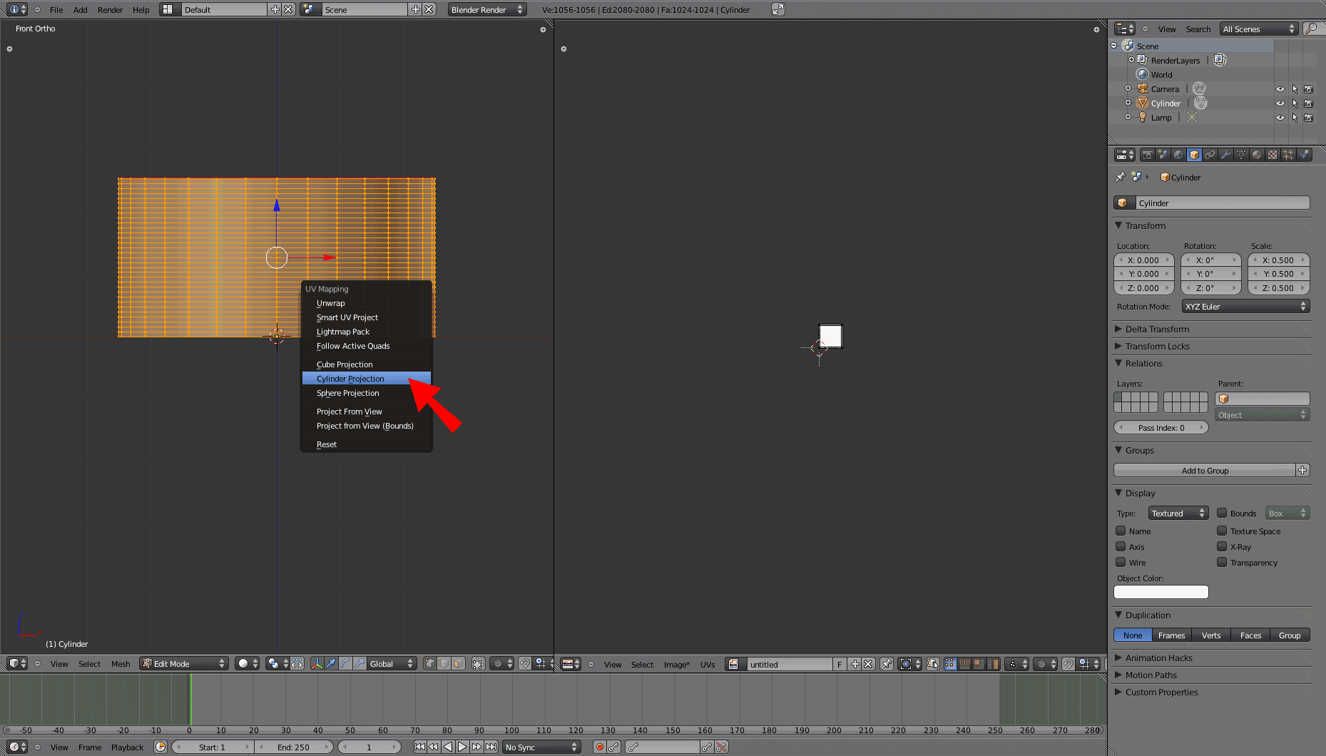
U>Unwrap
Just to see the UV map better zoom into it with your mouse wheel
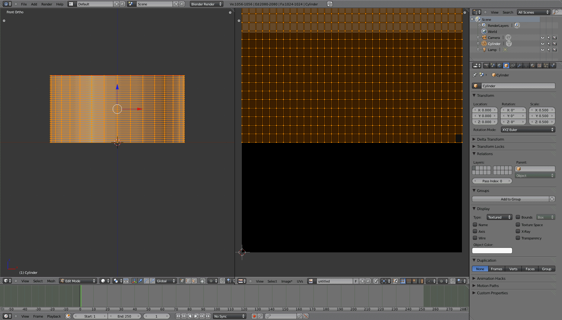
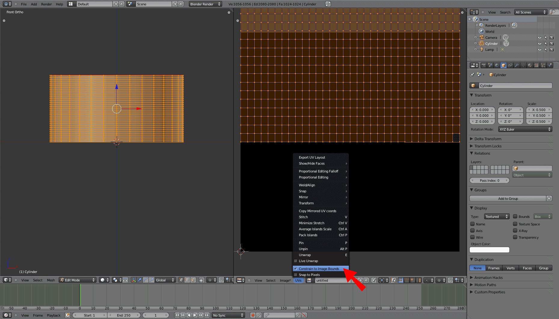
Blender created an UV map in the UV/Image Editor. You have to scale it exactly into the square texture field. But Blender has some handy features to help you - like UVs>Constrain to Image Bounds which you have to activate now.
This feature will constrain the UV Map to the image (texture) bounds while you move, scale or rotate it.
The UV Map has a rectangular shape, so you have to scale it to fit into the square image field. Use G to move and S to scale the map alternately.
With S-X you can scale the map width.
With S-Y you can scale the map height.
The result don't have to be exact.
Remark: The cylinder is made up of 32*33=1056 vertices. But the UV Map has 33*33=1089 vertices. That's why the vertices of the vertical seam exist twice in the UV Map. Between the vertices of the UV Map there are 32*32=1024 faces. Thats a square map. The final size of the sculpt map will be defined later.

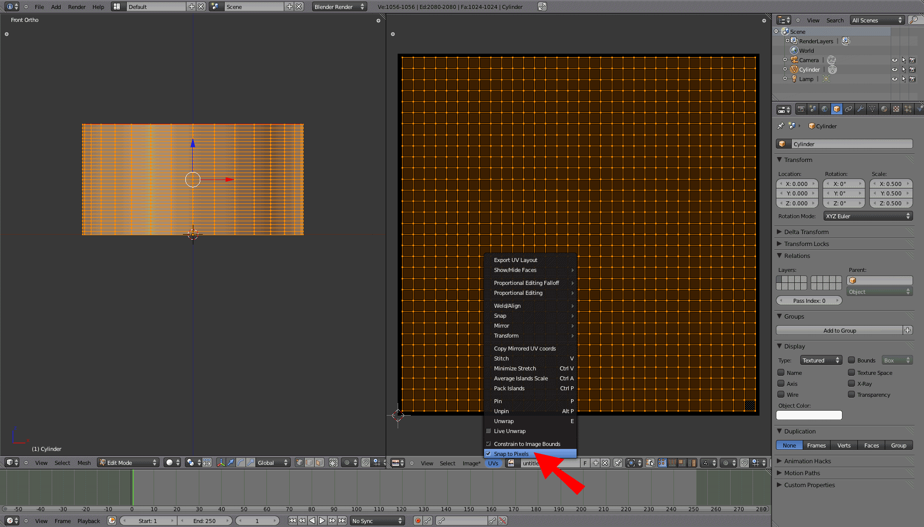
Now activate UVs>Snap To Pixels
As described before this makes it possible to snap the 32*32 faces of the UV map to the 32*32 pixels of the image while editing the UV map.
Use S to scale down the map a lil bit and immedatily scale it up to maximum. Then the vertices will snap exactly between the pixels of the image.
With S-X you can scale the map width.
With S-Y you can scale the map height.
The result has to be exact.

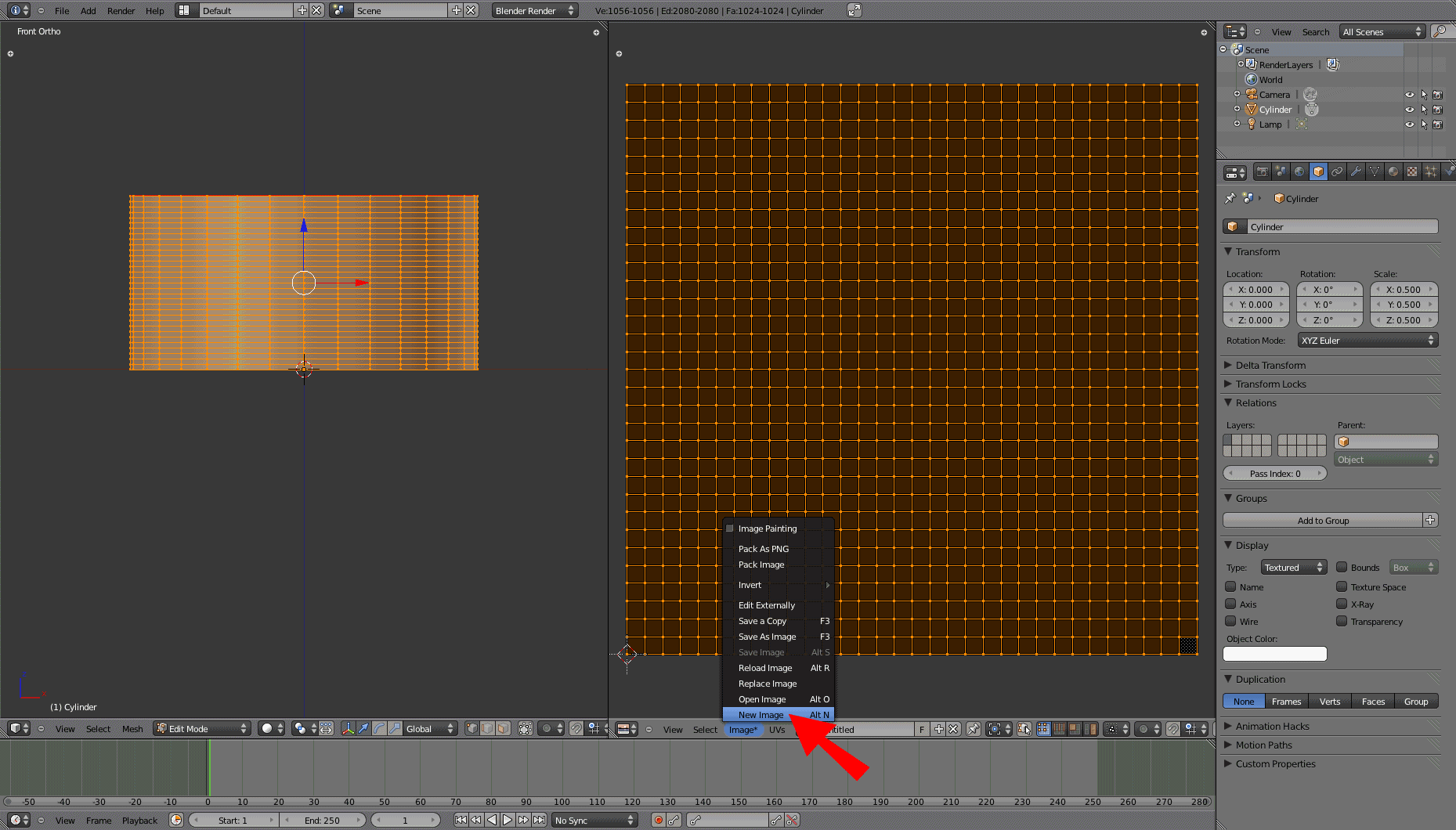
Now you have to create a new image again because you need a sculpt map with 64*64 pixels. Therefor
choose Image > New,
press ALT+N or
click the button NEW.
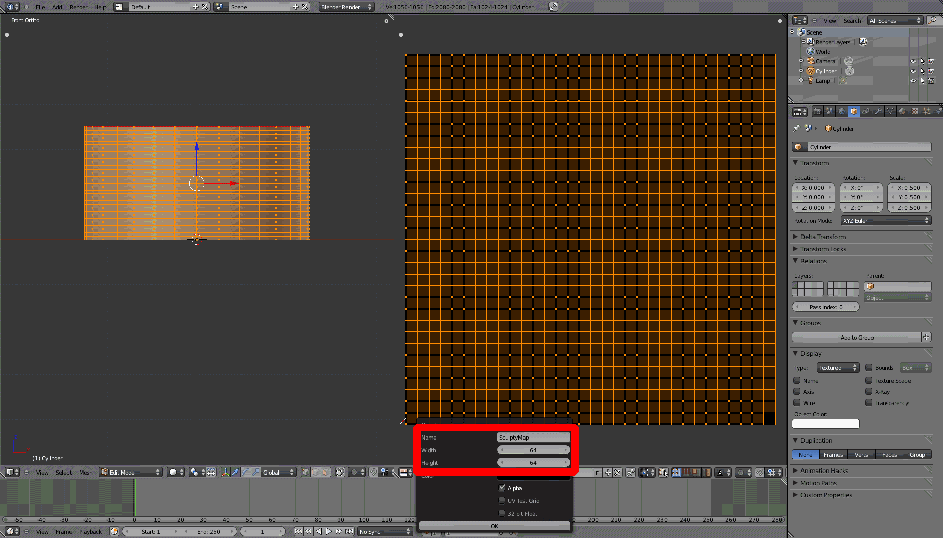
Choose this values
Name: SculptMap
Width: 64
Height: 64
and apply with OK.
Now your cylinder is unwrapped exactly to the UV map which will be filled with the baked SculptMap later.
Eventually you have to zoom out a lil bit with the mouse wheel to fit the UV map into the window.
Cube Oblong:
CubeOblong64, 32*128
It seems Blender really needs an image name to bake later, the default name 'untitled' don't work.
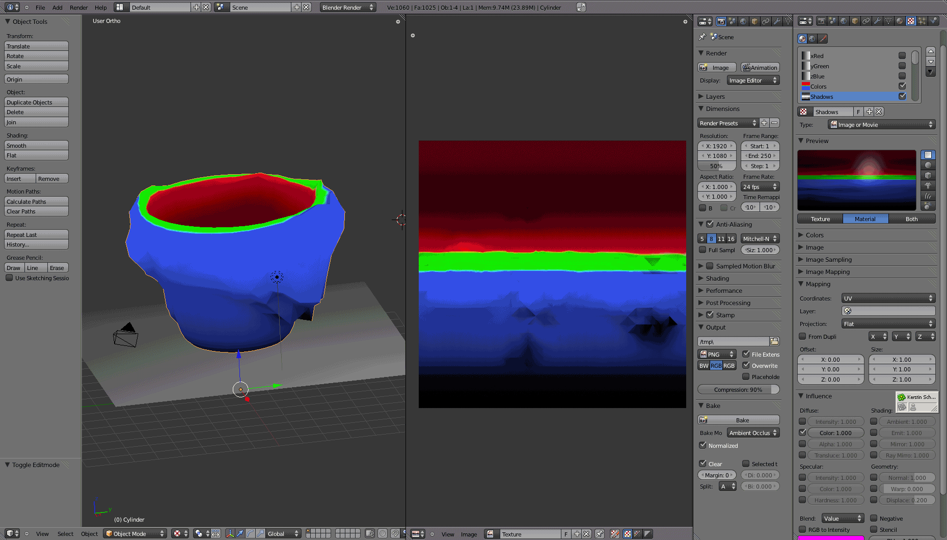
In the next steps you will add and define a material for the cylinder. This material will have three textures Red, Green and Blue. Each color stands for the axis x, y and z.
E.g. Red indicates the deforming of the cylinder along the x-axis, green for the y-axis and blue for the z-axis.
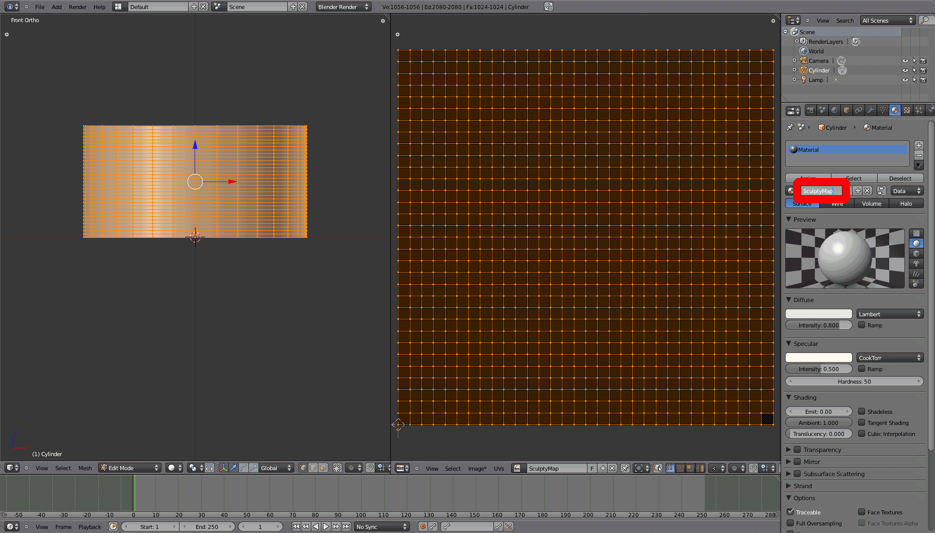
At first open the Material Buttons with F5.

To create a new material just click the button New.

Type in a unique name for the material, e.g. SculptyMap.
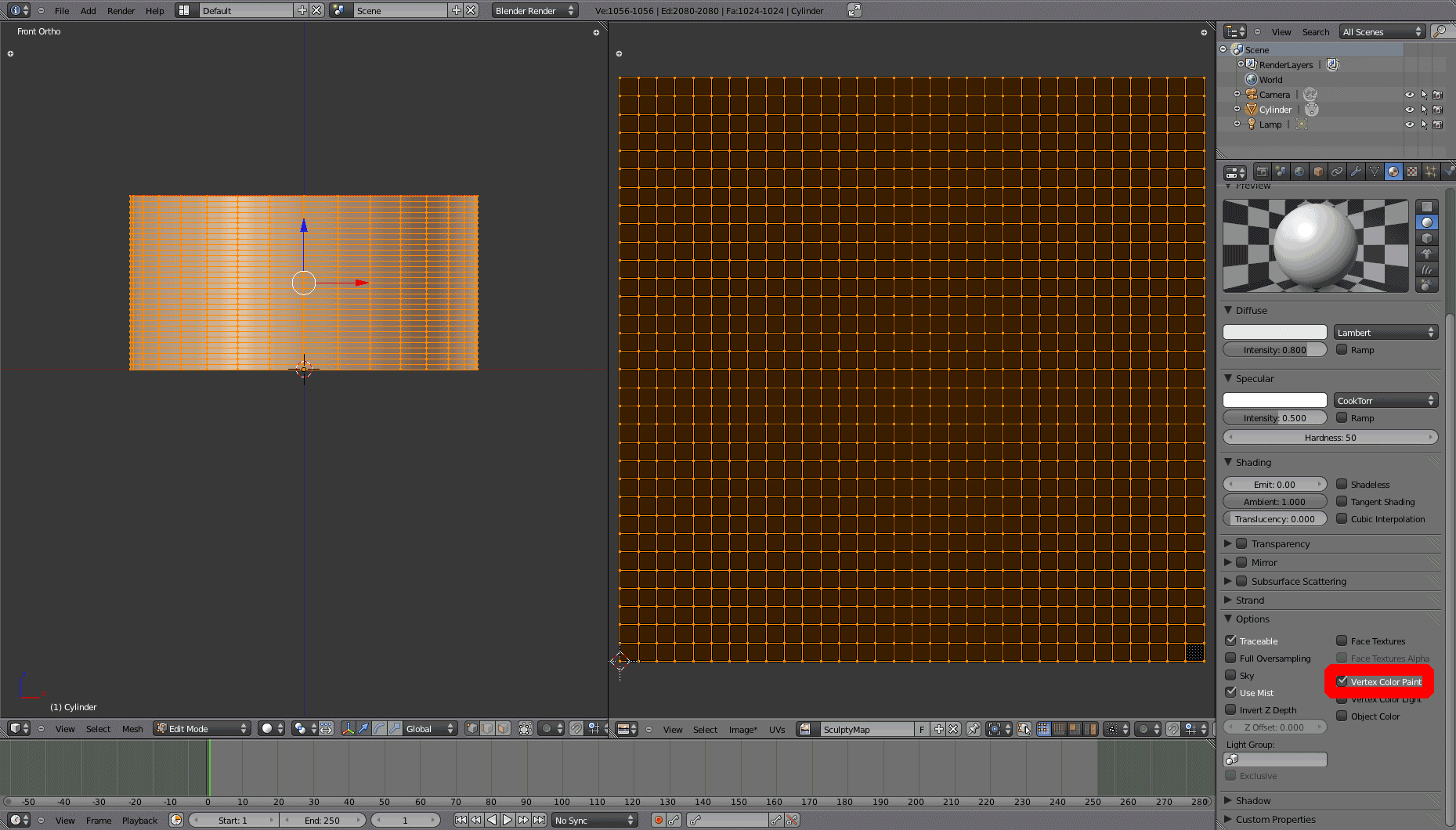
In the Options tab enable Vertex Color Paint.
Now Blender will overwrite the basic object color Specular Color with the three textures you will add in the next steps.
Hint: This makes it also possible to paint directly on your object in Vertex Paint mode to create a texture.
Next you need three textures, one for each color (red, green and blue). Each texture has to blend between dark and bright regarding to the cylinder coordinates.
Open the Texture Buttons.

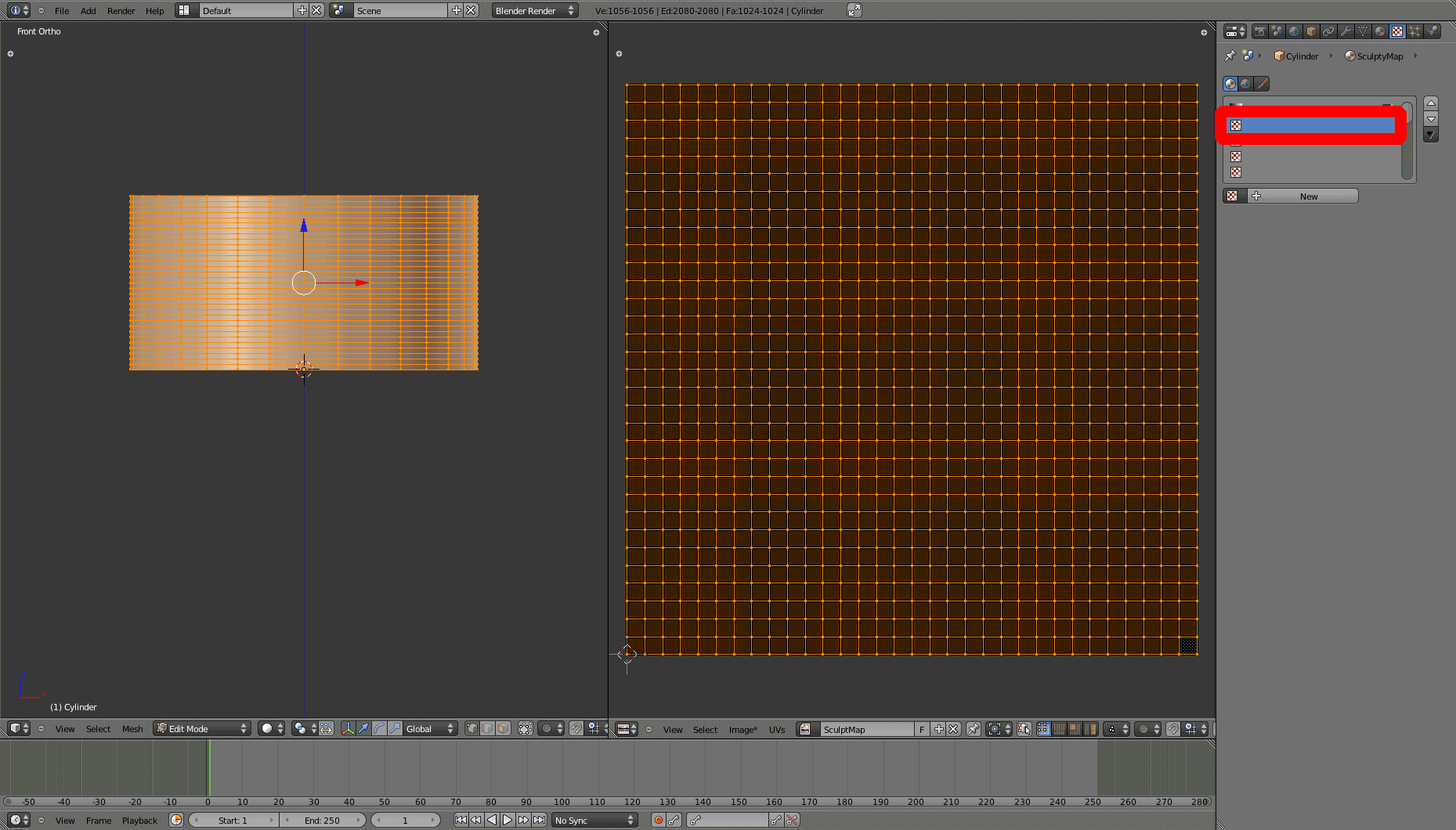
For the texture red select the first texture slot.

Press New to create the first texture.

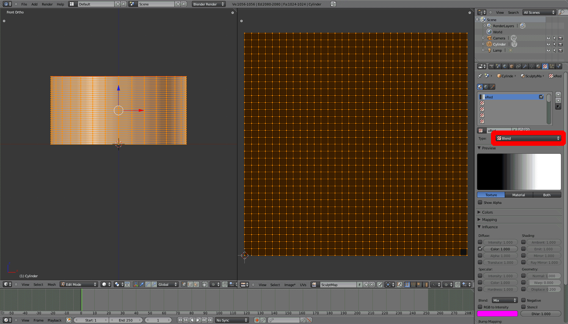
Type in a unique name for the texture, e.g. xRed

As Texture Type choose Blend.
In the Mapping tab you have to assign the texture to an axis, in this case X.
To do so switch the three selection boxes to
X - None - None.

In the Influence tab change the Blend mode to Add.
Now Blender will add the RGB values, so the cylinder shape and its deformations will be calculated into brightness differences for each color.

Set the texture color to red (1, 0, 0).

For the texture green select the second texture slot.
Press New to create the first texture.

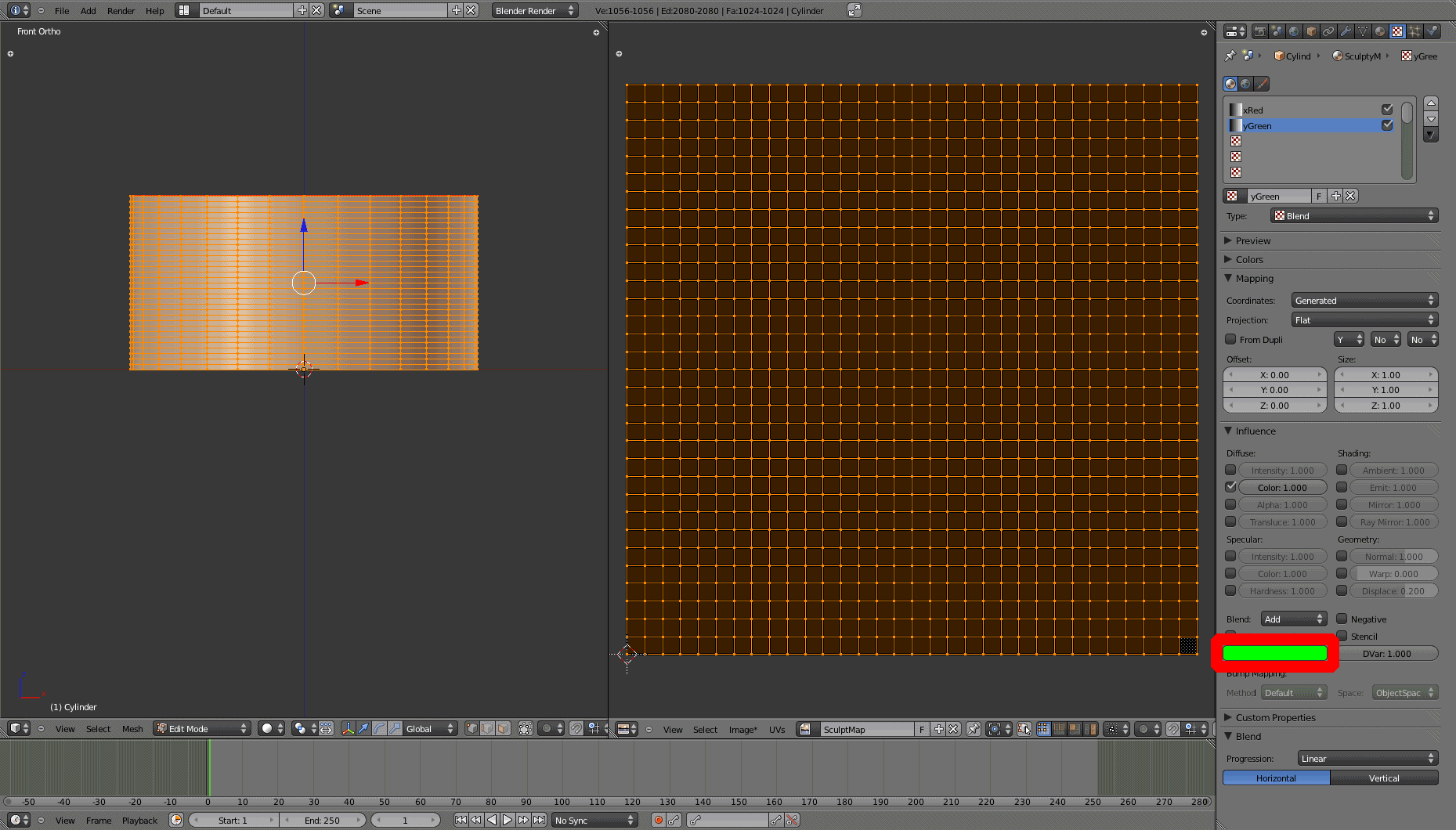
Type in a unique name for the texture, e.g. yGreen

As Texture Type choose Blend.

In the Mapping tab you have to assign the texture to an axis, in this case Y.
To do so switch the three selection boxes to
Y - None - None.

In the Influence tab change the Blend mode to Add.
Now Blender will add the RGB values, so the cylinder shape and its deformations will be calculated into brightness differences for each color.

Set the texture color to green (0, 1, 0).
For the texture blue select the third texture slot.

Press New to create the first texture.

Type in a unique name for the texture, e.g. zBlue

As Texture Type choose Blend.
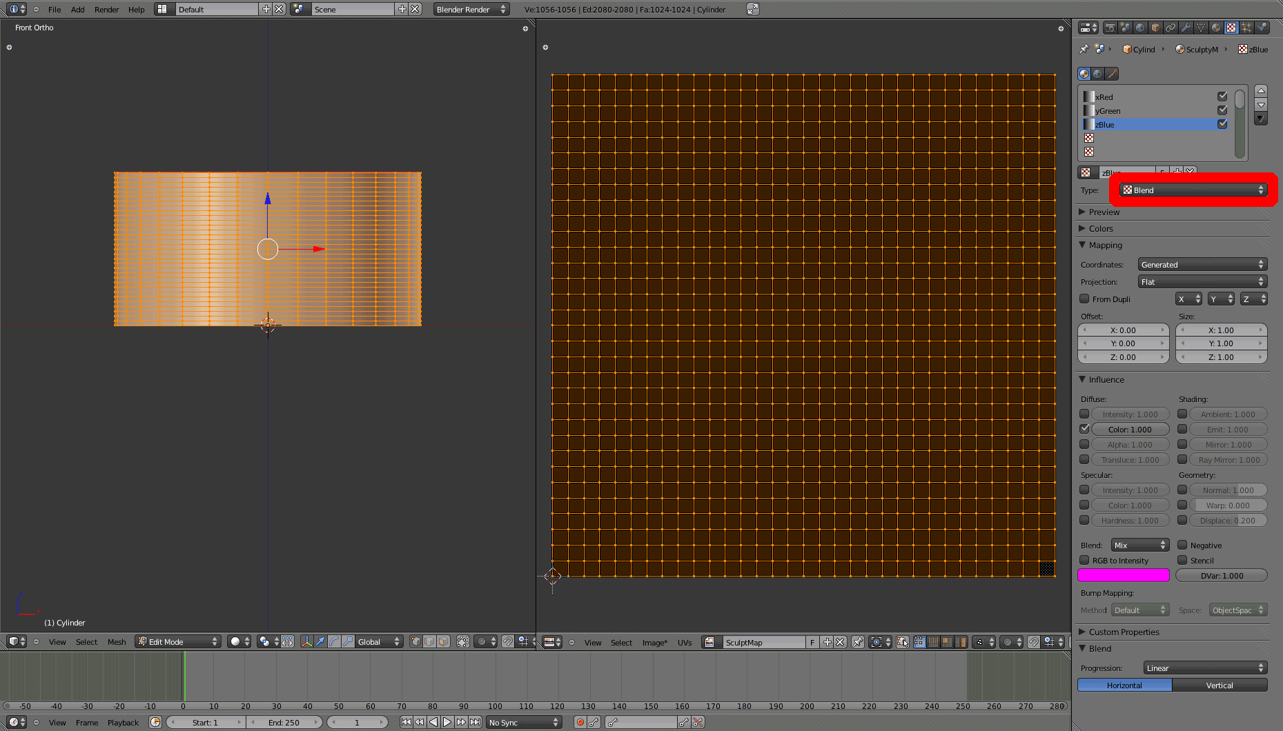
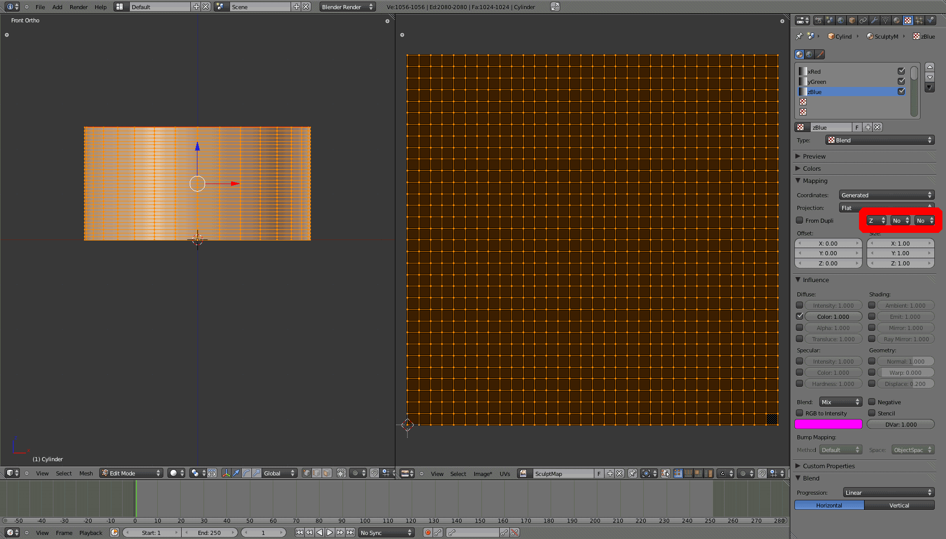
In the Mapping tab you have to assign the texture to an axis, in this case Z.
To do so switch the three selection boxes to
Z- None - None.
In the Influence tab change the Blend mode to Add.
Now Blender will add the RGB values, so the cylinder shape and its deformations will be calculated into brightness differences for each color.

Set the texture color to blue (0, 0, 1).

The material and its textures for your cylinder are defined now. That makes it possible to bake the shape of the cylinder into a planar UV-Map which you can use as SculptyMap.
To setup the final Baking open the Render Buttons.
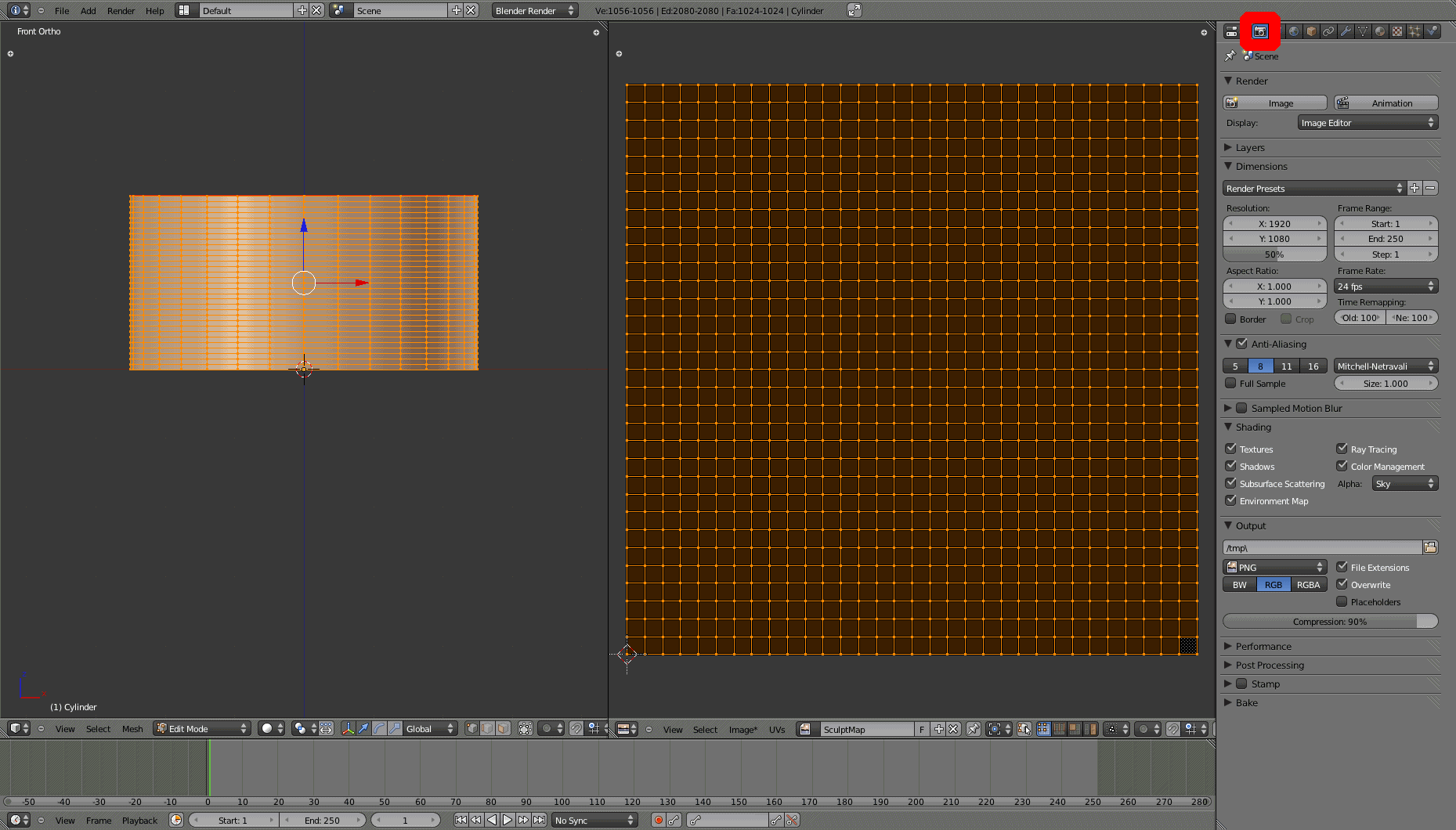
In the Shading tab disable the Color Managment. Otherwise Blender would calculate the wrong colors depending on your system, but we need a neutral result.

Select Textures as Bake Mode, so Blender will bake the three textures you defined into the resulting image.
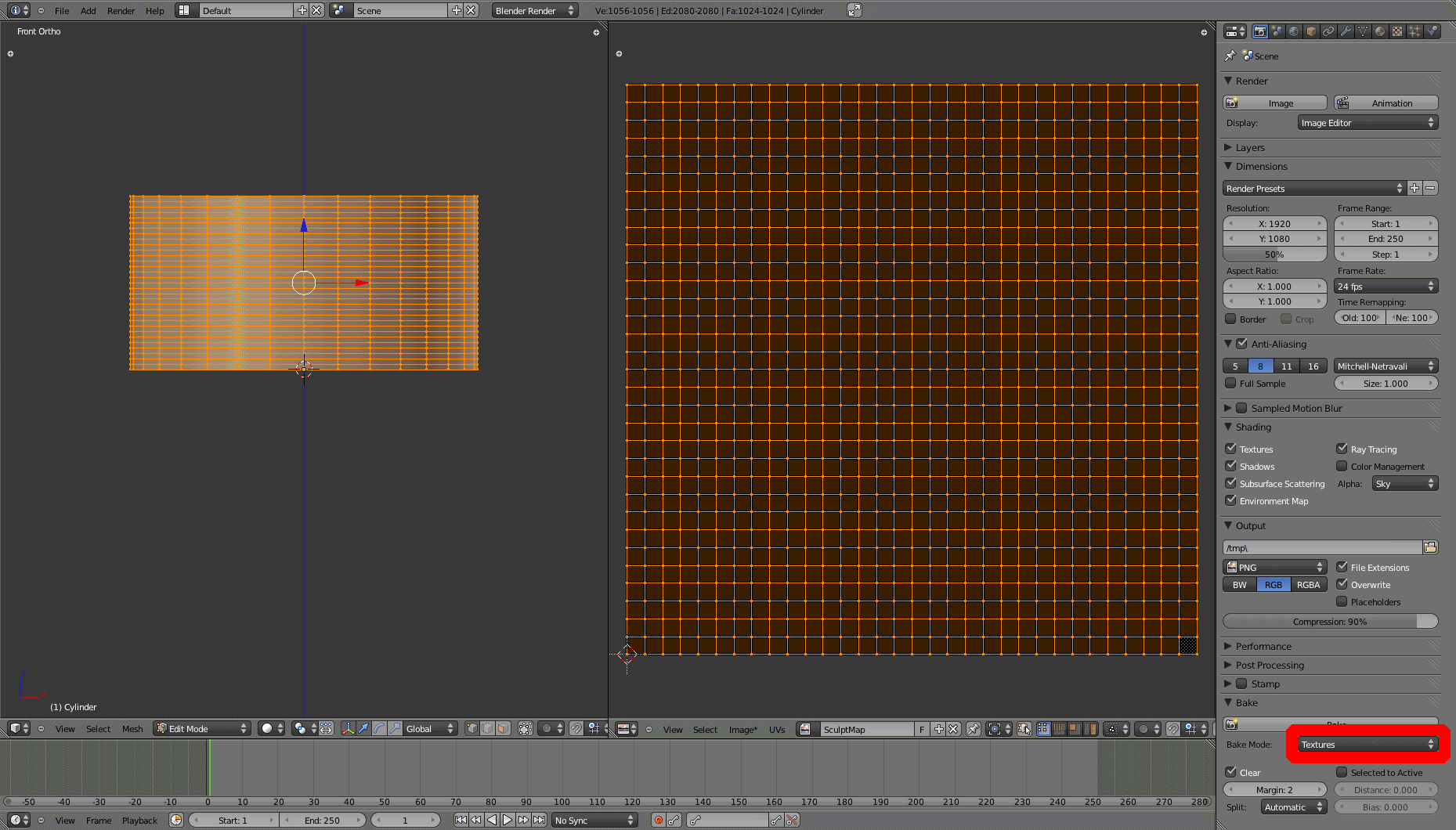
This has no effect on the baking result. But it is better while watching the baking process and for assessing the result. If disabled Blender will set the image in the UV/Image-Editor to black before each baking.
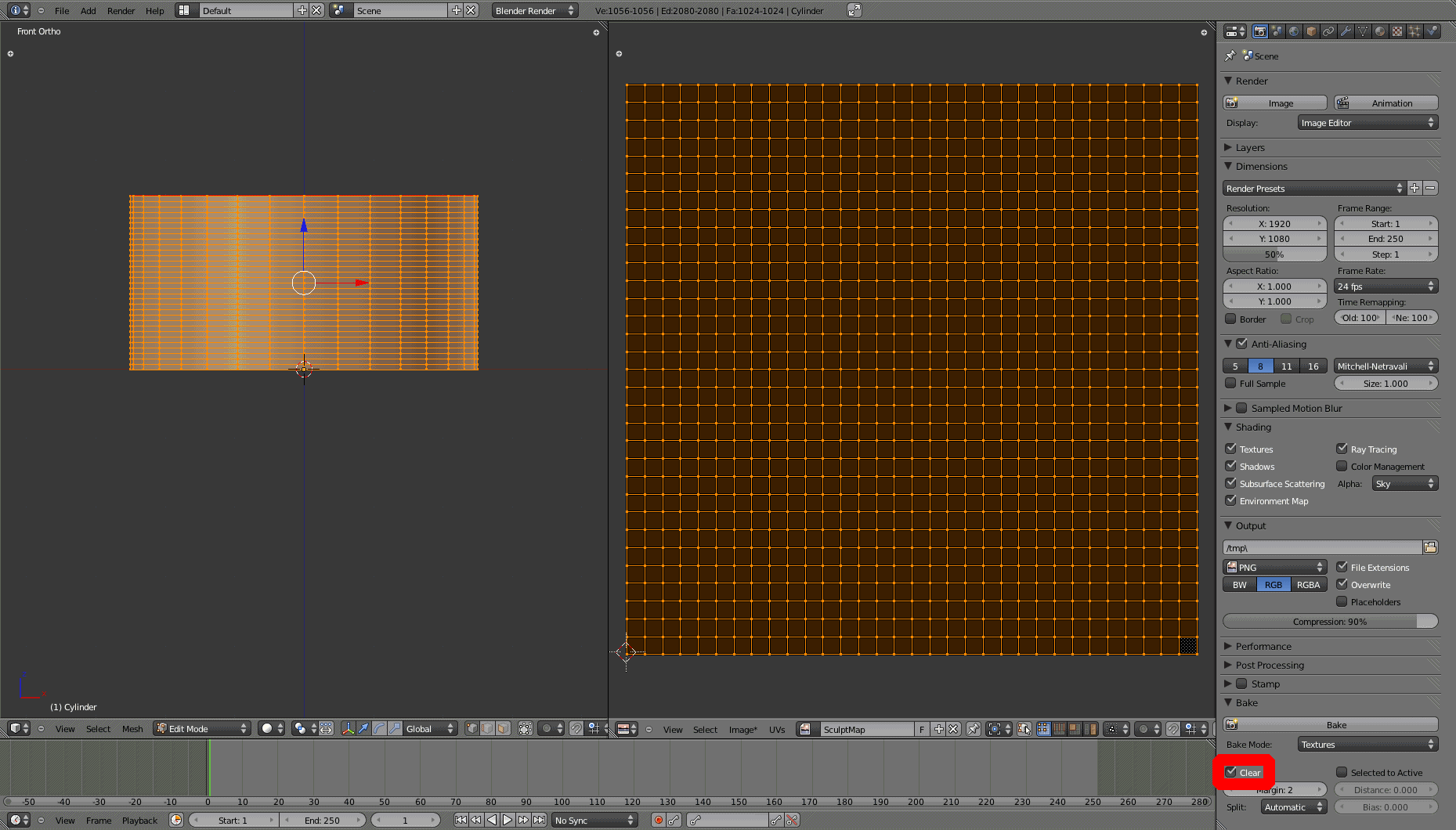
Set Margin to 0.
If set to 1 or higher Blender would make a post-baking process to overlap the image border with set pixel range. But you need to have the result exactly fitting into the 64*64 px image.

Now press the button Bake. You will get a result in the UV/Image-Editor with the typical rainbow colors. If it is different like shown here you made something wrong.
Hint: If you deform the object later it can happen that the bake result shows black triangles. That happens when vertices are too close to each other, so their faces collide. The poles of a sphere are a good example. One half of the quads don't receive light, so when they get baked into triangles one will be black.
To avoid this select the relevant vertices and press W>Smooth. That will open the poles a little bit. After baking you can undo this step again.

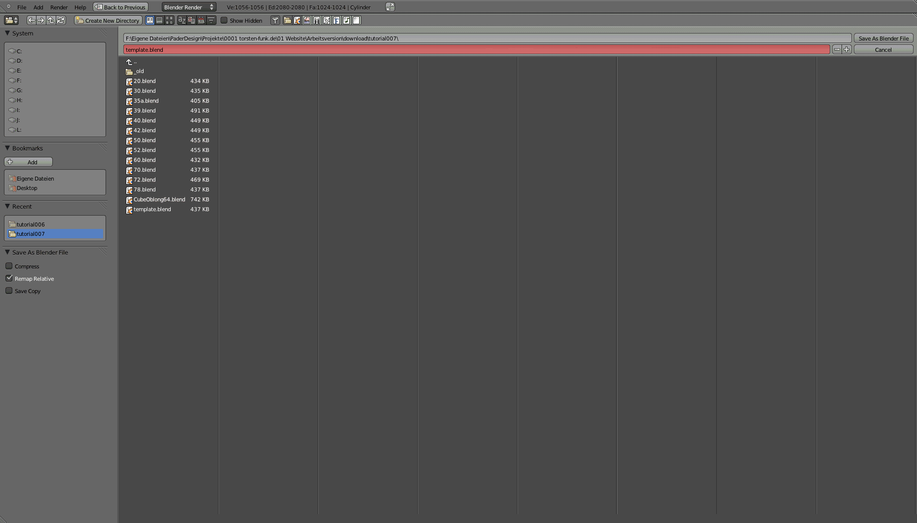
You should save now your work, e.g. as template.blend.
From now you only have to open this template, deforming the cylinder as you like and bake it again.
Save the UV-Map as TGA-File and upload it with lossless compression to Second Life or OpenSimulator. That's all!
Alternativ kannst Du das Template hier herunterladen: template.blend
Hint: If you like you can download the template.blend.
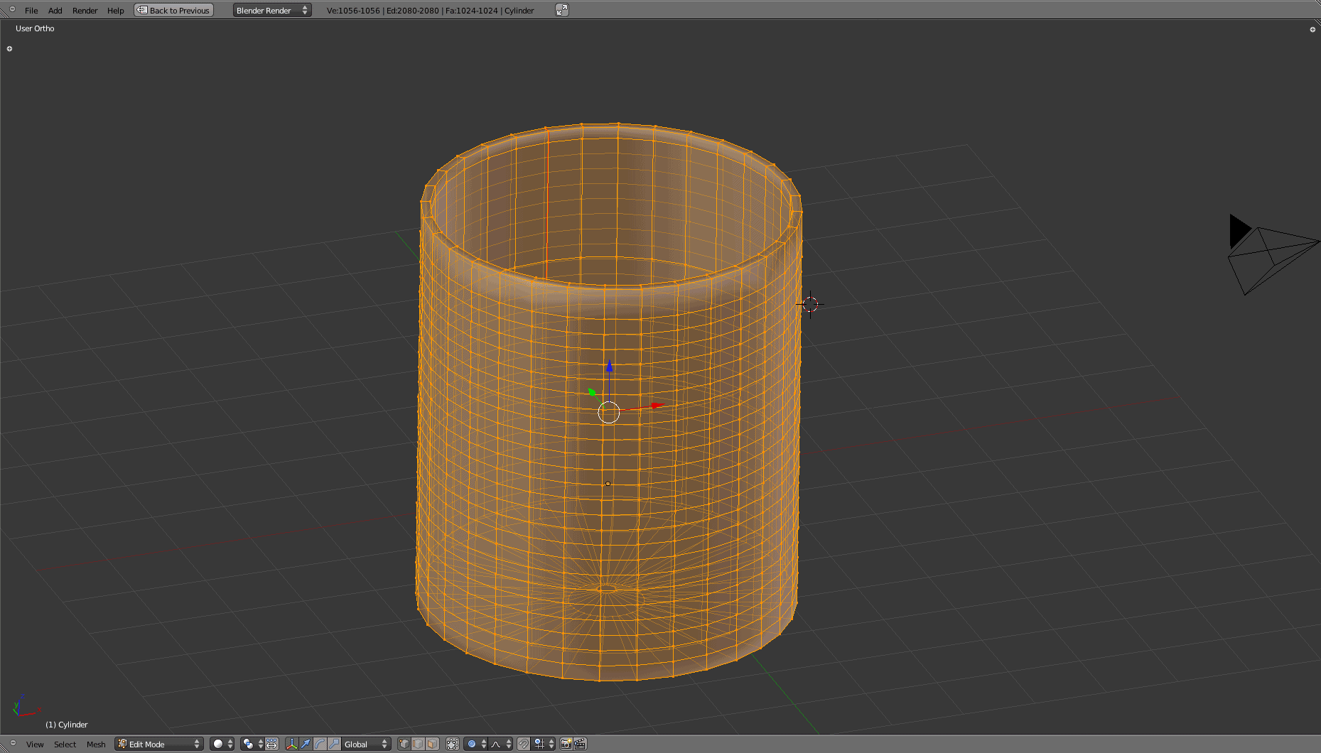
Tab to enter Edit Mode.
Press O to toggle Proportional Editing.
Mousewheel to skale Falloff Size.
Try different Falloff Types.
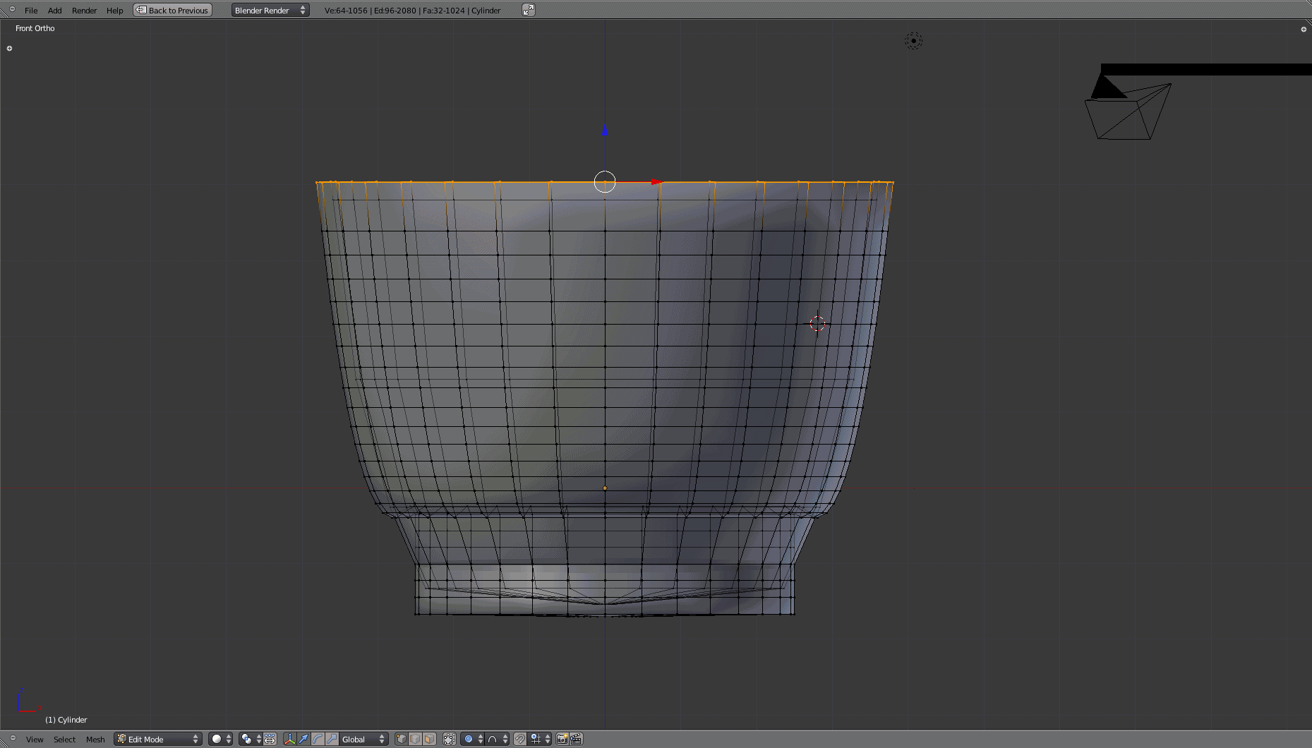
Switch to Sculpt Mode
Enable Tools bar with T.
Enable Front Faces Only.
LMB to Edit

Leave Edit Mode
Properties>Transform>Dimensions: 2.55*2.55*2.55
Properties>Display>
Scale: 0.0255
Subdivisions: 1
Move Object, so the leftmost vertice is on the Y-axis, the foremmost on the X-axis and the bottommost on the X-axis.
Go into Edit Mode.
Select problematic vertices.
Mesh>Snap>Selection To Grid
regarding LOD, cogs, ...

e.g. flowers, fern, piano forte padels, ...

e.g. candle with wick exactly at object center for fire particle emission.


evtl. at first adding a subsurf modifier to get a higher mesh resolution and to avoid hard edged triangles in the bake result.
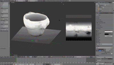
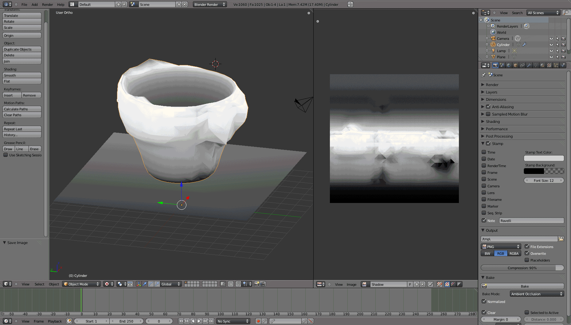
Create new image: Shadow, 1024, 1024
Plane under Object
Leave Edit Mode
World: Enable AO
World>Gather>Samples: 20
Render>Bake: Bake Mode: Ambient Occlusion
Normalized
Bake
...takes a while...
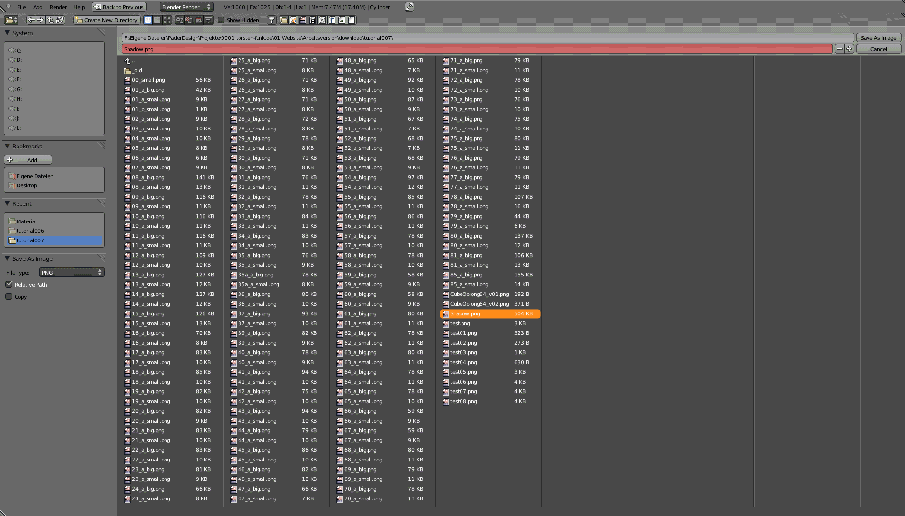
save image as Shadow.png
Switch to Textures


Enter Edit Mode
Add New Image:
Colors, 1024*1024, <0, 0, 0.25>
OK
Leave Edit Mode

Hide plane
Change to Texture Paint mode
evtl. switching on the color palette:
http://wiki.blender.org/index.php/Extensions:2.5/Py/Scripts/Paint/Palettes
Hint: http://wiki.blender.org/index.php/Doc:Manual/Materials/Vertex_Paint
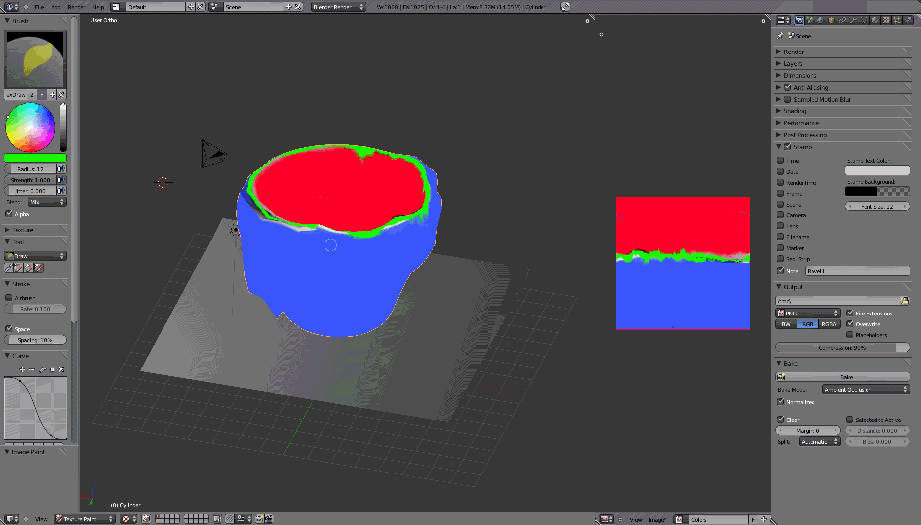
in UV/Image-Editor:
Enable Image>Image Painting
Optimize the texture
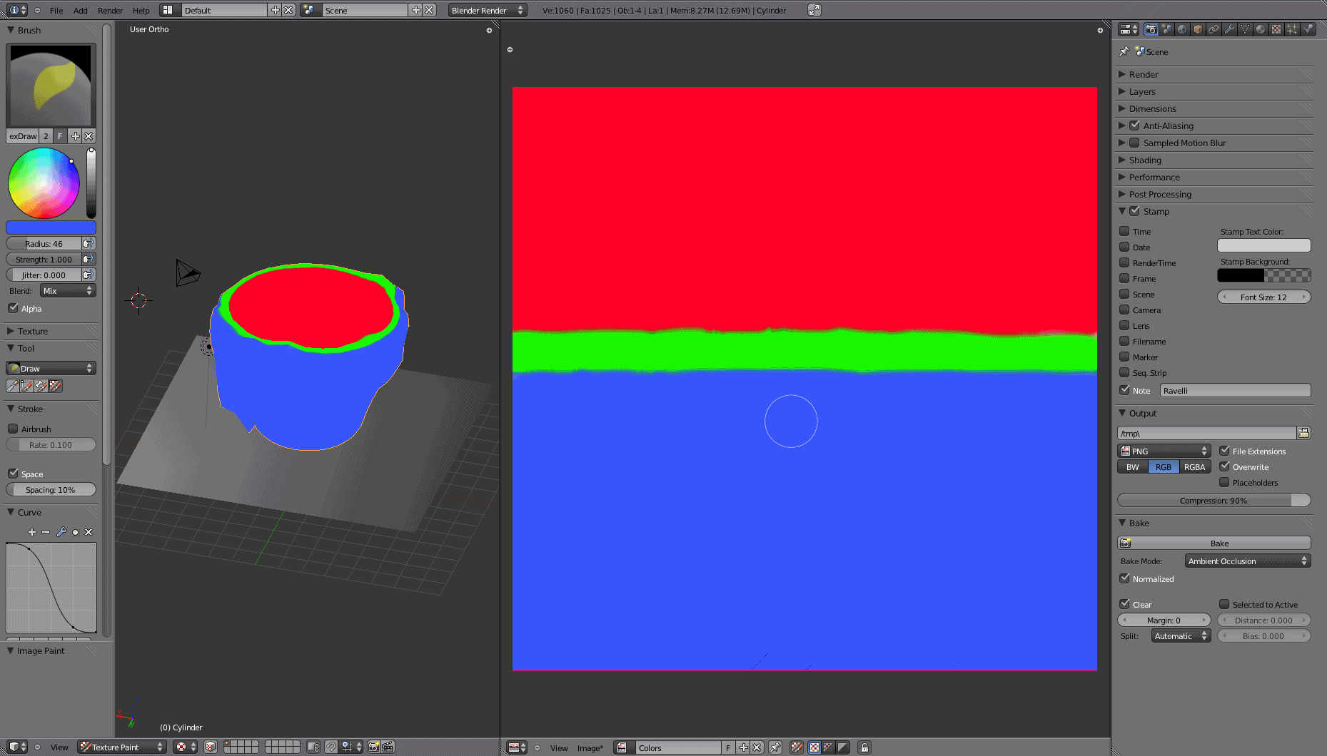
Colors.png

Enter Edit Mode
Add New Image:
Texture, 1024, 1024 (or less)
Material Buttons:
Click F to keep this material Colors
Add New Material: +, Texture
Disable Vertex Color Paint
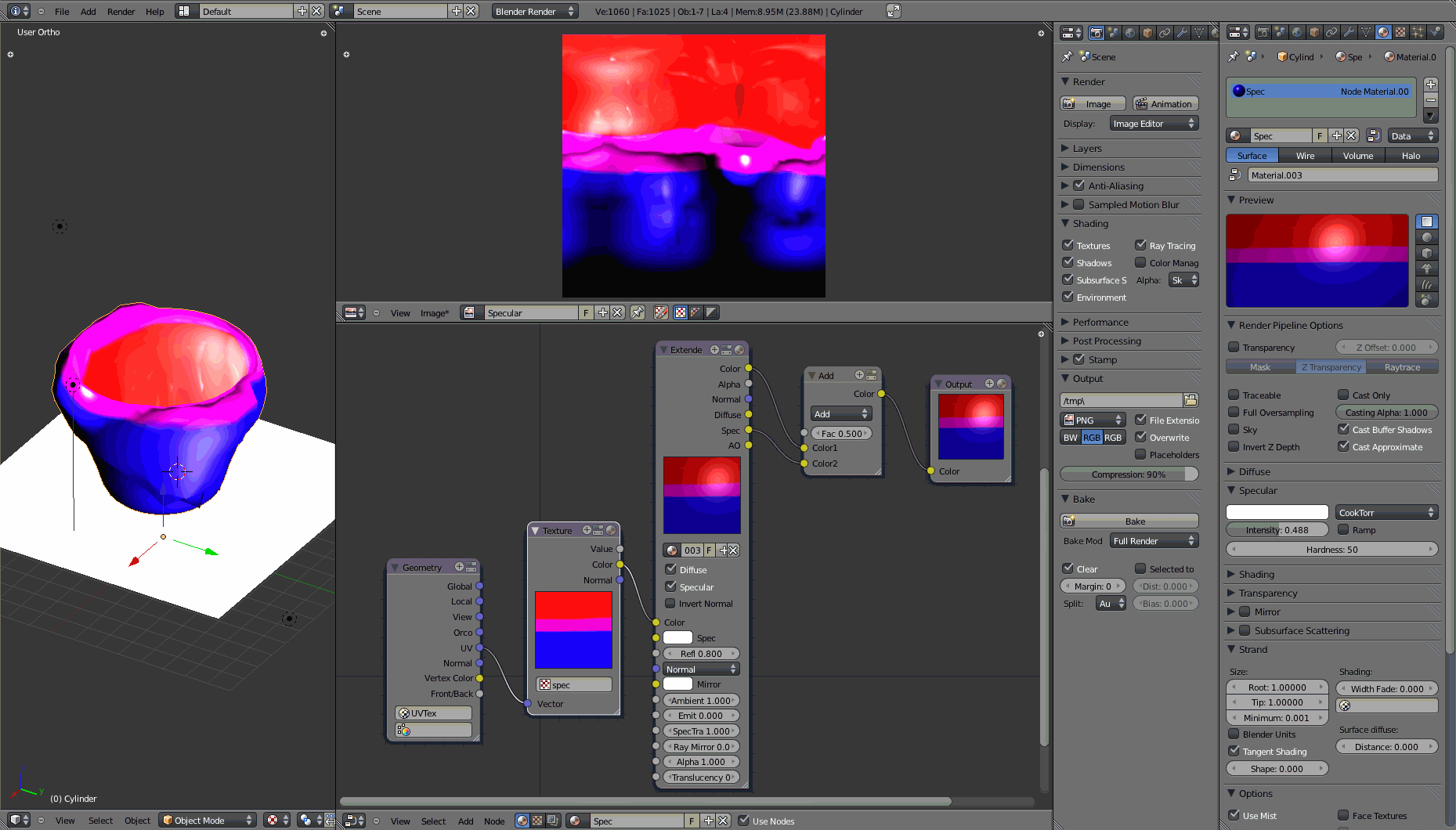
Texture Buttons:
Disable old textures
Add New Texture:
Colors, Image or Movies, Image: Colors, Mapping: UV, Influence>Blend: Mix
Preview: Material, Preview Type: Plane
Add New Texture:
Shadows, Image or Movies, Image: Shadows, Mapping: UV, Influence>Blend: Value
Change Influence>Color: 0.9
Render Buttons:
Bake>Bake Mode: Textures
Bake
Save texture as texture.png
evtl with Render>Stampsss


Gehe nun das Tutorial auch für andere Grundformen durch. Das für den Zylinder erstellte Material kannst Du dann einfach mitverwenden, so ersparst du dir viel Arbeit.
Hier als Beispiel ein paar Angaben bzgl. einer Sphere:
32*34
Pole entfernen => 1056 Vertices
Front-View
Alle Vertices markieren
Kugel einmal nach rechts drehen (Num6)
Unwrappen: Sphere from View
Layout Clipped to Image Size
einpassen
Neues Image: 32*32px
Snap to Pixels


www.torsten-funk.de.